
User's Manual

Chapter Two Installation
Man_455U Rev 1.0 Page 11
Chapter Two INSTALLATION
2.1 General
The 455U module has is housed in a rugged aluminium case suitable for DIN-rail mounting.
Terminals will accept wires up to 2.5 mm
2
in size.
Normal 110-240V AC supply should not be connected to any terminal of the 455U
module. Refer to Section 2.3 Power Supply.
To operate this equipment legally the user must obtain a radio operating license from the
government agency. This is done so the government can coordinate radio users in order to
minimize interference.
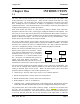
Before installing a new system, it is preferable to bench test the complete system.
Configuration problems are easier to recognize when the system units are adjacent.
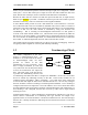
Following installation, the most common problem is poor communications caused by
incorrectly installed antennas, or radio interference on the same channel, or the radio path
being inadequate. If the radio path is a problem (ie path too long, or obstructions in the way)
then higher performance antennas or a higher mounting point for the antenna may rectify the
problem. Alternately, use an intermediate 455U Module as a repeater.
The foldout sheet 455U Installation Guide provides an installation drawing appropriate to
most applications. Further information is detailed below.
Each 455U module should be effectively earthed via the "GND" terminal on the 455U
module - this is to ensure that the surge protection circuits inside the 455U module are
effective.
2.2 Antenna Installation
The 455U module will operate reliably over large distances. The distance which may be
reliably achieved will vary with each application - depending on the type and location of
antennas, the degree of radio interference, and obstructions (such as hills or trees) to the radio
path. The expected range for radio data rates of 19200 bits/sec (with 25Khz bandwidth) is 30
km line-of-sight. At 9600 bit/sec (with 12.5Khz), the expected distance will be approx 35
km.
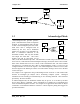
Where it is not possible to achieve reliable communications between two 455U modules, then
a third 455U module may be used to receive the message and re-transmit it. This module is
referred to as a repeater.
An antenna must be connected to each 455U module using the female SMA connector at the
top of the module.
To achieve the maximum transmission distance, the antennas should be raised above
intermediate obstructions such that the radio path is true “line of sight”. Because of the
curvature of the earth, the antennas will need to be elevated at least 5 metres above ground for
paths of 5 km. For short distances, the modules will operate reliably with some obstruction of
the radio path. Obstructions which are close to either antenna will have more of a blocking