
User's Manual

Chapter Two Installation
Man_455U-D Rev 3.01 Page 27
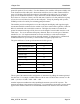
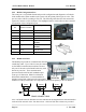
and may be engaged by operating the single DIP switch in the end plate next to the RS485
terminals. The DIP switch should be in the “1” or “on” position to connect the resistor. If the
module is not at one end of the RS485 cable, the switch should be off.
2.5 Discrete I/O Point
The 455U-D provides a single connection which can be used as a discrete input for alarms, or
a discrete output, to control remote equipment,
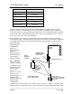
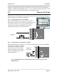
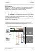
2.5.1 Using the Discrete I/O as an Output
When using the DIO pin as an output, it acts as an NPN
transistor to common. It can be wired to an indicator or alarm
(max 30VDC, 500mA) or to a relay to remotely operate
equipment. The output is controlled using the AT#O
command (AT#O0 turns off, AT#O1 turns on).
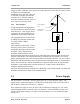
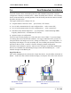
2.5.1 Using the Discrete I/O point as an Input
When using the DIO pin as an input, it is activated by connecting the DIO pin to COMMON,
This can be done using a voltage free
contact (Relay or Switch) or a NPN
transistor to common. To read the
status of the Input, ensure the output
function is disabled (AT#O0) and
read S-Register S33.
Note: The DIO channel is not available when the 455U unit is part of a Dual
Redundant pair.
_
+
DC
Load
Max 30VDC
0.5A
B
A
GND
+24
+12
DIO
455U
DIO
DIO
GND
Voltage-free
contact input
B
A
GND
+24
+12
DIO
455U
V
+
V
-