
User's Manual

Chapter Two Installation
Man_455U-D Rev 3.01 Page 25
2.4 Serial Connections
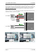
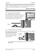
2.4.1 RS232 Serial Port
The serial port is a 9 pin DB9 female and provides for
connection to a host device as well as a PC terminal for
configuration, field testing and for factory testing.
Communication is via standard RS232 signals. The 455U-D
is configured as DCE equipment with the pinout detailed
below. Hardware handshaking using the CTS/RTS lines is
provided. The CTS/RTS lines can be configured to reflect
the status of the local unit’s input buffer. The 455U-D
supports XON/XOFF flow control.
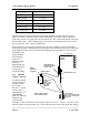
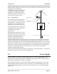
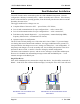
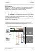
Example cable drawings for connection to a DTE host (a PC) or another DCE host (or modem)
are detailed below.
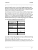
DB9 Connector Pinout
Pin Name Direction Function
1 DCD Out
Data carrier detect –
- driven when link is established in Acknowledged mode
- driven when module is online in unacknowledged mode
2 RD Out
Transmit Data from modem – Serial Data Output
3 TD In
Receive Data into modem – Serial Data Input
4 DTR In
Data Terminal Ready - DTR can be configured to initiate low power
mode, or to force a link disconnection (“hang up” in Acknowledged
mode.
5 SG
Signal Ground
6 DSR Out
Data Set Ready - always high when unit is powered on.
7 RTS In
Request to Send - hardware flow control configurable
8 CTS Out
Clear to send - hardware flow control configurable
9 RI Out
Ring indicator - indicates another module is attempting to connect in
Acknowledged mode.
455U
DB9
MALE
DTE HOST
DB9
FEMALE
455U
DB9
MALE
DCE HOST
DB9
MALE