
User's Manual

905U-D Radio Modem Module User Manual
Page 20 © May 2000
unit does not receive the acknowledgment, the DCD output will reset. When the connection
is made (DCD set), the 905U-D units can transmit data to each other.
The destination address may be configured two ways. The AT&Z command (see Section 4,
Configuration) enters an “auto-dial” address. The ATD command enters a “single-dial”
address. The AT&Z command only has to entered once, and the 905U-D remembers the
destination address. The ATD command has to be used each time a connection is to be
made - the 905U-D will not remember the previous destination address. If an auto-dial
address is configured, the master will transmit the “connect” message every ten seconds
until it receives an acknowledgment. If a single-dial address , the master unit will try to
connect five times - if no acknowledgment is received, a “BUSY” or “NO ANSWER”
response is sent to the host connected to the master. The host must then issue the ATD
dial command to the 905U-D before it will try to connect again.
The auto-dial operation is similar to a fixed line modem, where the destination address is
always the same. Once the auto-dial address is configured, it does not need to be entered
again. If the communications link fails (DCD resets), the master unit will automatically send
connect messages to re-establish the link.
The single-dial operation is similar to a dial-up modem. The 905U-D will make a connection
to another unit only when it is told to by the host device. If the communications link fails for
any reason, the master unit will not send a connect message until it receives another ATD
command.
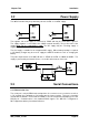
Either of the two modules at the end of the link can be the “master” unit - the “master” unit
has the responsibility of establishing the radio link and periodically checking the link. Data
can be transferred in both directions - from the “master” to the “slave” and from the “slave”
to the “master”.
Once the communications channel has been established, the 905U-D unit will accept input
data and send radio messages with data. On the RS232 port, if CTS/RTS is enabled, the
CTS signal will be active when the input data buffer is not full, AND the RTS signal at the
destination module is active. The local CTS/RTS status will reflect the remote CTS/RTS
status, as well as the local input buffer. Note that CTS/RTS is disabled in the default
configuration - if this feature is required, it must be enabled (refer Configuration Chapter 4).
If CTS/RTS is not enabled, then data will be lost after the input buffer (8KB) is full.
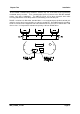
When a 905U-D unit receives a radio message, it will check the system address and
destination address, and also the error-check (optional). If these are correct, it will return a
ACK (acknowledgment) message to the source unit. If the system address or destination
address is not correct, then no return message is sent. If the addresses are correct, but
the error-check incorrect, then a NACK (error) message is sent to the source unit.
If the source unit receives a NACK message, or does not receive any message within 1
second, it will re-transmit the same message. It will attempt to transmit the message up to
five times, with a 5 second delay between attempts. If the unit still does not receive an ACK
message after five attempts, it will reset the DCD LED, and reset the DCD output. The
unsuccessful message will be held in the input buffer until the communications link is re-
established. If the source module is the “master” unit, then it will immediately send
“connect” messages every ten seconds to the “slave” unit. If the source module was the
“slave” unit, then it will wait until it receives a “connect” message from the “master” and the
communications channel is re-established.
During normal operation, if there has been no radio activity for a period (called the “update”
period), the “master” unit will transmit the “connect” message to check the radio path. The
update period is a time configured by the user.