
User's Manual

Chapter Six Troubleshooting
Man_905UD_2.0.doc Page 39
Chapter Six TROUBLESHOOTING
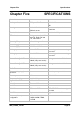
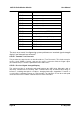
6.1 Diagnostics Chart
INDICATOR CONDITION MEANING
OK LED OFF Continuously
• Power supply failure
• CPU failure
OK LED ON Continuously
• Normal Operation
Radio TX LED ON Flashes briefly
• Radio transmitting
Radio RX LED ON GREEN flash
RED flash
• Radio receiving data
• Weak radio signal
Serial RX LED ON GREEN flash
RED flash
GREEN continuously
• Serial Port Receiving
• CTS low
• Configuration Mode
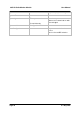
Radio RX and Serial RX LED
ON
RED flash for 10 secs
after power up
•
Configuration corruption
(EEPROM failure)
Serial TX LED ON Flashes briefly
• Serial port transmitting
DCD LED ON Continuously
•
In transparent mode, always
on.
•
In controlled mode, a radio link
has been established.
The green OK LED on the front panel indicates correct operation of the unit. This LED
extinguishes on failure as described above. When the OK LED extinguishes shutdown state
is indicated. On processor failure, or on failure during startup diagnostics, the unit shuts
down, and remains in shutdown until the fault is rectified.
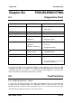
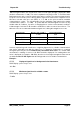
6.2 Test Functions
6.2.1 Diagnostic Functions - AT &Tx
To aid in the checking and setup of the 405U unit diagnostic functions in the 405U are
provided using the standard Hayes AT commands. Several of these functions are used
during factory test, and will not work correctly if the unit is not connected to the factory test jig.
The table below outlines the functions of the various tests: