
User's Manual


Appendix A Switch Configuration
Man_905UD_2.0.doc Page 55
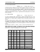
Data
Bits
Start
Bits
Stop
Bits
Parity CTS/ RTS
control
VALUE
7 1 1 even disabled 0 0 0 0 1 1 0 0
7 1 1 odd disabled 0 0 0 0 1 1 0 1
8 1 2 none disabled 0 0 0 0 1 1 1 0
7 1 2 even disabled 0 0 0 0 1 1 1 1
7 1 2 odd disabled 0 0 0 1 0 1 0 0
1.1.9 Connect Update Time
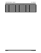
PARAM = 1 1 1 0 Default = 0 1 1 0 0 1 0 0
In controlled mode, the 405U unit will transmit a “connect” message if there has been no
activity on the radio channel for the update time. The connect update time value is the 8-bit
binary equivalent of the desired time in 0.1 minute increments. Hence for a desired hold-off
time of 1 minute, a VALUE code of ten (00001010 ) is entered. For the maximum time of
25.5 minutes, a VALUE code of 255 (11111111) is entered. The default update time is 10
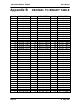
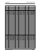
minutes. Appendix B lists the 8-bit patterns for each value between 0 and 255.
1.1.10 Reset to Factory Default Settings
The following switch pattern will reset the configurations to the factory default values. Note
that this also includes the original factory set system address.
•
Enter the code with and press button
until Serial RX LED indicates RED.
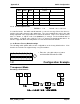
1.2 Configuration Example
Transparent Mode
Extending a PLC Network
1 1 0 0 0 0 0 0
0 0 0 0 0 0 0 0