
User's Manual


905U-D Radio Modem Module User Manual
Page 48 © May 2000
Note that repeater and destination addresses are only entered for the “master” unit
in each link. For “slave” units, only the unit address is entered. For modules which will just
act as a repeater unit, just a unit address need be entered. For these modules, enter the exit
pattern of all zero’s after the unit address.
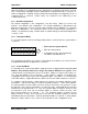
To select controlled mode the following switch pattern is entered after the system address
has been entered.
• First enter the system address
• Enter the unit address
•
Enter the repeater addresses (if any)
in order, and then enter the
destination address.
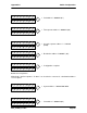
• When all of the addresses have
been entered
• Enter all 0’s
•
Configuration mde will automatically
exit and the RX LED will reset.
The operating mode will be set to Controlled Mode with Error-Checking (mode 7) - refer to
Appendix A – Section 1.1, Configuration Parameters.
Example
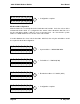
Module #1 Configuration
Module #1 is configured as the master unit .
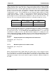
• System address 100 1001 0001 0010.
Source Repeater Repeater Destination
#1 ----------------> #2 -----------------> #100 --------------------> #3
#101
Apart from being a repeater in the 1 - 3 link, 100 is also in a separate link to 101
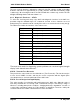
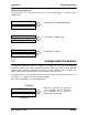
----- ADDRESS -----
0 0 0 0 0 0 0 1
0 0 0 0 0 0 0 0
0 1 0 0 1 0 0 1
0
0 0 0 0 0 0 0 0
0 0 0 1 0 0 1 0