
User's Manual


Appendix A Switch Configuration
Man_905UD_2.0.doc Page 47
Once the module is in configuration mode, transparent or controlled mode may be selected.
This is achieved by entering in another switch pattern. If transparent mode is selected, no
further configuration is required, and the module will automatically exit configuration mode. If
controlled mode is selected, further entries are required for the addressing of the
communications link.
1.0.1 Default Configuration
The default configuration is the configuration set in the factory. When you receive new
modules, they will have this configuration. The default configuration is transparent mode
without error-checking, autoconnect mode, with serial data rates of 9600 bits/sec, and radio
data rate of 4800 bit/sec. The serial ports will be set up for a byte format of 8 data bits, 1
start bit, 1 stop bit and no parity. Further details of default settings are included in Appendix A
– Section 1.1.10.
1.0.2 Transparent Mode
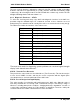
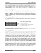
To select transparent mode the following switch pattern is entered after the system address
is entered :-
• First enter the system address
• Enter the switch pattern
•
Configuration mode will automatically
exit and the RX LED will reset.
The operating mode will be set to mode 4 (Transparent mode without error check). Refer to
Configuration Parameters in Appendix A – Section 1.1.
1.0.3 Controlled Mode
In controlled mode, each module within a network must be configured with an individual unit
address. Each module must have a unique unit address within the one system. Each
controlled mode system may have up to 127 modules. Addresses may be in the range 1 to
127. Note that address 0 is not accepted - if this address is entered, the module exits
configuration mode and you must start configuration again. This address is coded in binary
on the DIP switches. Appendix B lists the switch code for each address between 1 and 127.
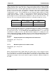
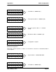
To configure controlled mode, switch patterns are entered consecutively with the module
unit address, any repeater addresses and the destination address. These switch patterns
are entered after the system address has been entered. If more than one repeater is used in
the radio link, then each repeater address is entered in order, starting with the first repeater
and then the next repeater and so on. Up to five repeater addresses may be entered. If only
one repeater is used, then only one repeater address is entered. If three are used, then
three repeater addresses are entered - etc. The destination address is always the last
address entered. If there are no repeaters used, then the destination address is entered
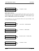
immediately after the unit address. After the destination address is entered, a switch pattern
with all “0”s (all the switches off) is entered. The module then exits configuration mode.
0 0 0 0 0 0 0 0
0 0 0 0 0 0 0 0