
User's Manual


905U-D Radio Modem Module User Manual
Page 42 © May 2000
The tone reversals function is initiated by setting all of the DIL switches to ON, and holding
down the red button for approximately 5 seconds (until the Serial RX LED indicates RED
continuously). On releasing the button, the RX LED will flash continuously, and the TX LED
will light, indicating that the radio transmitter is on.
6.2.2 Diagnostic Functions - AT&Tx
To aid in the checking and setup of the 405U unit diagnostic functions in the 405U are
provided using the standard Hayes AT commands. Several of these functions are used
during factory test, and will not work correctly if the unit is not connected to the factory test jig.
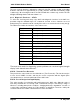
The table below outlines the functions of the various tests:
Test Command Function
AT&T0 Factory test only
AT&T1 Factory test only
AT&T2 Factory test only
AT&T3 Factory test only
AT&T4 Factory test only
AT&T5 Internal RAM test
AT&T6 Nonvolatile Memory (EEPROM) test
AT&T7 Configuration Switch test
AT&T8 Received Signal Strength Display
AT&T9 Transmit Tone reversals
AT&TA BER Test - Master
AT&TB BER Test - Slave
AT&TC BER Test – Two direction
The tests most useful for diagnosing system problems are “received signal strength
display” and “transmit tone reversals”.
AT&T9 - Transmit Tone Reversals
This provides the same function as described above (Tone Reversals). This function may be
used to check VSWR of aerials, and may be used in conjunction with the Signal option
(described below) to check the path between two 405U units.
AT&T8 - Received Signal Strength Display
This option provides for testing the radio path between two 405U units. Although a pair of
units may communicate successfully, radio communication may be affected by a range of
influences, including atmospheric conditions, changing landscape, degradation of aerials or
co-axial cable, low battery voltage etc. Fade margin is an indication of how far a radio path
can deteriorate before reliable communication becomes unreliable.