
User's Manual

Chapter Six Troubleshooting
Man_905UD_2.0.doc Page 41
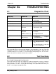
Chapter Six TROUBLESHOOTING
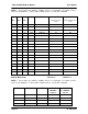
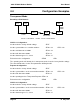
6.1 Diagnostics Chart
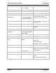
INDICATOR CONDITION MEANING
OK LED OFF Continuously
• Power supply failure
• CPU failure
OK LED ON Continuously
• Normal Operation
Radio TX LED ON Flashes briefly
• Radio transmitting
Radio RX LED ON GREEN flash
RED flash
• Radio receiving data
• Weak radio signal
Serial RX LED ON GREEN flash
RED flash
GREEN continuously
• Serial Port Receiving
• CTS low
• Configuration Mode
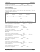
Radio RX and Serial RX LED
ON
RED flash for 10 secs
after power up
•
Configuration corruption
(EEPROM failure)
Serial TX LED ON Flashes briefly
• Serial port transmitting
DCD LED ON Continuously
•
In transparent mode, always
on.
•
In controlled mode, a radio link
has been established.
The green OK LED on the front panel indicates correct operation of the unit. This LED
extinguishes on failure as described above. When the OK LED extinguishes shutdown state
is indicated. On processor failure, or on failure during startup diagnostics, the unit shuts
down, and remains in shutdown until the fault is rectified.
6.2 Test Functions
6.2.1 Radio Testing using Tone Reversals
This function allows the unit to be configured to continuously transmit a sequence of alternate
zeros and ones on the radio. This function provides the facility to check VSWR of aerials
during installation, as well as checking the fade margin of the path between two units (see
below - received signal strength indication).