
User's Manual


905U-D Radio Modem Module User Manual
Page 18 © May 2000
Chapter Three OPERATION
3.1 Power-up and Normal Operation
When power is initially connected to the 905U-D module, the module will perform internal
diagnostics to check its functions. The following table details the status of the indicating
LEDs on the front panel under normal operating conditions.
LED Indicator Condition Meaning
OK On Normal Operation
Radio RX GREEN flash
RED flash
Radio receiving data
Weak radio signal
Radio TX Flash Radio Transmitting
Serial RX GREEN flash
RED flash
GREEN continuously
Serial Port Receiving
CTS low
Configuration Mode
Serial TX GREEN flash Serial Port Transmitting
DCD On Transparent mode - always on
Controlled mode - on when
communications link is established
DCD Off Communications failure or link not
established
Other conditions indicating a fault are described in Chapter Six Troubleshooting.
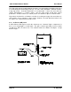
Low Power Operation
The 905U-D may be forced to a low power condition where it switches off its receiver -
power consumption is reduced to approx 20% of normal. The low power condition will occur
if the 905U-D is configured for controlled mode (modes 6 or 7), AND if an autodial address is
configured, AND if the low power mode feature is configured in the “character type”
selection, AND if the DTR signal is “low” or “off”.
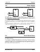
The use of this low power operation may be applicable in remote locations where there is a
limited power supply such as solar panels. In this situation, the DTR signal from the host
device is used to “wake-up” the 905U-D unit. The 905U-D unit will then operate normally until
the DTR signal is reset by the host device.