
User's Manual


Chapter Two Installation
Man_905UD_2.0.doc Page 13
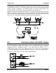
An aerial should be connected to the module via 50 ohm coaxial cable (eg RG58 or RG213)
terminated with a male BNC connector. The higher the aerial is mounted, the greater the
transmission range will be, however as the length of coaxial cable increases so do cable
losses. For use on unlicensed frequency channels, there are several types of aerials
suitable for use. It is important aerials are chosen carefully to avoid contravening the
maximum power limit on the unlicensed channel - if in doubt refer to an authorised service
provider.
Connections between the aerial and coaxial cable should be carefully taped to prevent
ingress of moisture. Moisture ingress in the coaxial cable is a common cause for problems
with radio systems, as it greatly increases the radio losses. We recommend that the
connection be taped with a layer of PVC insulating tape, then a layer of vulcanising tape such
as “3M 23 tape”, with a final layer of PVC insulating tape.
Where aerials are mounted on elevated masts, the masts should be effectively earthed to
avoid lightning surges. Although the 905U-D module is fitted with surge protection, additional
surge suppression devices are recommended if lightning surge problems are experienced. If
the aerial is not already shielded from lightning strike by an adjacent earthed structure, a
lightning rod may be installed above the aerial to provide shielding.
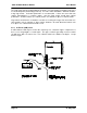
2.2.1 Dipole aerial.
A unity gain dipole is the normal aerial for use on unlicensed channels. As it does not provide
any gain, then the power transmitted from the aerial will be the same as the power out of the
module, and hence will not exceed the permitted power of the unlicensed channel.
For marginal radio paths, the following lengths are the recommended maximum for the
coaxial cable to the dipole aerial. RG58 10 metres RG213 20 metres. Note that this
applies to marginal paths only - if the radio path has a strong radio signal, then longer
lengths of cable ( and hence more cable loss) can be tolerated. If more than 20 metres of
cable is required for a marginal path installation, then a low loss cable such as RG9913
should be used. Alternatively, a higher gain aerial may be used to compensate for losses.
Dipole aerials should be mounted vertically, at least 1 metre away from a wall or mast.
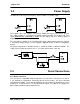
2.2.2 Three element Yagi aerial.
A 3 element Yagi aerial provides approx 4 dB of gain. This may be used to compensate for
coaxial cable loss for installations with marginal radio path. Note that these aerials should not
be used if the coaxial cable lengths are less than the following minimum lengths, otherwise
the power transmitted from the aerial will exceed the power permitted for the unlicensed
channel.
RG58 10 metres
RG213 20 metres.
Yagi aerials are directional. That is, they have positive gain to the front of the aerial, but
negative gain in other directions. Hence Yagi aerials should be installed with the central
beam horizontal and must be pointed exactly in the direction of transmission to benefit from
the gain of the aerial. Also note that Yagi aerials normally have a drain hole on the folded
element - the drain hole should be located on the bottom of the installed aerial.