
User's Manual

Radio/Serial Telemetry Module User Manual
Page 10 © March 2000
Chapter Two INSTALLATION
2.1 General
The 905 module is housed in a rugged aluminium case, suitable for DIN-rail mounting. Terminals are
suitable for cables up to 2.5 sqmm in size.
Normal 110/220/240V mains supply should not be connected to any input terminal of the
905 module. Refer to Section 2.3 Power Supply.
Before installing a new system, it is preferable to bench test the complete system. Configuration
problems are easier to recognise when the system units are adjacent. Following installation, the
most common problem is poor communications on the radio channel or the serial channel. For radio
modules, problems are caused by incorrectly installed aerials, or radio interference on the same
channel, or the radio path being inadequate. If the radio path is a problem (i.e. path too long, or
obstructions in the way), then higher performance aerials or a higher mounting point for the aerial
may fix the problem. Alternately, use an intermediate 905 module as a repeater.
For serial modules, poorly installed serial cable, or interference on the serial cable is a common
problem.
The foldout sheet 905 Installation Guide provides an installation drawing appropriate to most
applications. Further information is detailed below.
Each 905 module should be effectively earthed via a "GND" terminal on the 905 module - this is to
ensure that the surge protection circuits inside the 905 module are effective.
2.2 Power Supply
The 905 power supply is a switch-mode design which will accept either AC or DC supply. The 905
module may also be powered from a solar panel without an external solar regulator.
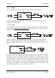
The 905 module accepts supply voltages in the following ranges :
12 - 24 volts AC RMS or 15 - 30 volts DC at the “supply” terminals, or
10.8 -15 volts DC at the “battery” terminals.