
User's Manual

Chapter Four Configuration
man_905_2.0.doc Page 31
Warning - do not allocate the address number 1 to a 905-3 module.
In addition to these network configurations, operational parameters called User Options may be
configured to change the features of the 905 operation. These parameters may be configured using
the Configuration Software of configuration switches (see 905 Switch Configuration Manual)
4.2 Easy Configuration Using Default Settings
If your application requires only a single pair of 905 modules, communicating via radio or serial link,
default settings may satisfy your needs. If so, no configuration is required. Essentially, all inputs at
Module A are reflected at the corresponding outputs at Module B. All inputs at Module B are
reflected at the corresponding outputs at Module A.
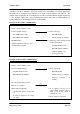
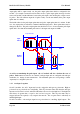
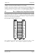
For 905-1 modules, the default configuration is as follows :-
In this configuration, the “PO” Pulse output is inactive and no special action is taken on “Comms
fail”, “Mains fail” or “Battery Low”. “DI 1” is configured as a digital and not a pulse input.