
User's Manual

Radio/Serial Telemetry Module User Manual
Page 8 © March 2000
These modules can transmit I/O messages hundreds of kilometres via the trunked radio system.
105M-1, 2 and 3 modules differ only in their input/output (I/O) design, and can interface to
105U and 105S modules. For more information, refer to the 105M User Manual.
• The 905U-C module provides an interface between host devices such as PLC’s or SCADA
computers, and a radio telemetry system comprising 905U and 105S radio telemetry modules.
The 905U-C allows 905U/105S modules to act as remote wireless I/O for the host devices.
For more information, refer to the 905U-C User Manual.
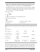
Product naming convention:
1 0 5 a - x
where a is:
U = UHF radio + RS232/RS485 serial S = RS232/RS485 serial only
M = MAP27 trunked radio interface
and x is:
1 = Input / Output module 2 = Input module ( includes one output)
3 = Output module C= Interface module
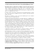
905U-1 105S-1 905U-2 105S-2 905U-3 105S-3
Radio ü ü ü
Serial ü ü ü ü ü ü
Digital Inputs (DI)
4 4
Digital Outputs (DO)
4 (relay) 1 (FET) 8 (FET)
Analogue Inputs (AI)
2 (4-20mA) 6 (0-20mA)
Analogue Outputs (AO)
2 (4-20mA) 8 (0-20mA)
Pulse Inputs (PI)
1 (100Hz) 4 (1x1KHz, 3x100Hz)
Pulse Outputs (PO)
1 (100Hz) 4 (100 Hz)
Comments
PI is DI 1. PO is
separate to DO.
PI’s are the same as
DI’s.
PO’s are the same as
DO’s (DO 1-4).
The module includes power supply, microprocessor controller, input/output circuits, RS485/232
serial port, and a UHF radio transceiver - no external electronics are required. The 905U version
has both radio and serial port communications. The 105S version does not have a radio and has
only serial communications. The 905U radio frequency has been selected to meet the requirements