
User's Manual

Chapter Two Installation
man_905_2.0.doc Page 25
Chapter Three OPERATION
3.1 Power-up and Normal Operation
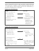
When power is initially connected to the 905 module, the module will perform internal diagnostics to
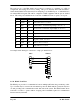
check its functions. The following table details the status of the indicating LED’s on the front panel
under normal operating conditions.
LED Indicator Condition Meaning
OK On Normal Operation
RX Occasional flash Radio Receiving, or
Activity on serial ports
RX Flashes continuously Configuration Mode
RX On Button press when entering
Configuration Mode
TX
(only on 905U units)
Occasional flash Radio Transmitting
PWR On Supply voltage available
from Solar Panel or
SUP1/SUP2
OK Flashes every 5 seconds +24V Supply
overloaded
Additional LED’s provide indication of the status of digital inputs and outputs. LED’s display the
status of each digital input (lit for active), and LED’s display the status of each digital output (lit for
active). Other conditions indicating a fault are described in Chapter Six Troubleshooting.
The 905 module monitors the power supply and provides status of supply failure and battery low
voltage for "mapping" to one of the module's own outputs or transmitting to a remote output.
When the 905 module is powered from a normal supply (i.e. via either of the “SUP” terminals), the
PWR LED indicator is lit. When the 905 modules is powered from a solar panel and battery, the
PWR LED indicator is lit only when the charge current is available (i.e. when the solar panel is
receiving light). In the event of excessively low battery voltage (10.8V), the OK LED will go off, the
unit will automatically set all outputs off, and disable the +24V analogue loop supply. the OK LED
will turn on again after the battery voltage exceeds 11.3V. This enables installations to be
configured so that the battery current drain is minimised in the event of extended mains failure,
reducing the possibility of deep discharge of batteries.
3.1.1 Communications
If transmissions are not successful, then the 905 module will re-try up to four times at random
intervals to transmit the message. If communications is still not successful, the “Comms Fail” internal
status will be set. In the default configuration, this will have no consequence and the 905 module will