
User's Manual

Chapter Two Installation
man_905_2.0.doc Page 19
2.4.3 Digital Outputs (905-2 and 905-3)
The digital outputs on the 905-2 and 905-3 modules are transistor switched DC signals, FET
output to common rated at 30VDC 500 mA. The 905-2 provides one digital output and the 905-
3 provides eight digital outputs. The first four DO’s on the 905-3 module are also the pulse outputs
- that is, the first four DO's can be either digital outputs or pulse outputs. The function of each of
these outputs may be configured individually. For a description of pulse outputs, refer to Section
2.4.7.
Digital outputs may be configured to individually turn off if no command message is received to that
output for a certain period. This feature provides an intelligent watch dog for each output, so that a
communications failure at a transmitting site causes the output to revert to a known state. See
Chapter 4 Configuration for further details.
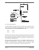
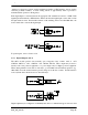
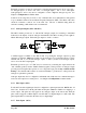
The output circuit is connected to the appropriate pair of "DO" terminals. Each digital output circuit
includes a LED indicator which is lit when the digital output is active.
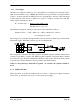
2.4.4 Analogue Inputs (905-1 and 905-2)
The 905-1 module provides two 4 - 20 mA DC analogue inputs for connecting to instrument
transducers such as level, moisture, pressure transducers, etc. The 905-2 module provides six 0 -
20 mA DC analogue inputs. Note that the inputs on the 905-2 module will measure down to 0mA,
so they can also be used for zero based signals such as 0 - 10 mA.
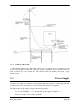
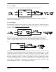
Each analogue input has a positive and negative terminal, and may be placed at any point in the
current loop, as long as neither input rises above the 24 volt supply level. Each input has a loop
resistance of less than 250 ohms and zener diode protection is provided against over-voltage and
reverse voltage, however additional protection may be required in high voltage or noisy
environments.
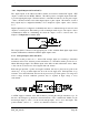
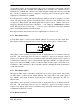
A 24VDC supply is available on the 905 module for powering the analogue transducer loops. In
this case, the analogue loop should be connected between a "AI 1-" terminal and "COM" ( for the
first analogue input) or "AI 2-" ( for the second analogue input), and so on for other inputs. The
positive terminal ("AI 1+" or "AI 2+", etc) should be connected to "+24V".