
User's Manual

Radio/Serial Telemetry Module User Manual
Page 14 © March 2000
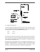
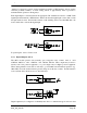
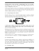
2.3.1 AC Supply
The AC supply is connected to the "SUP1" and "SUP2" terminals as shown below.
+
-
The AC supply should be "floating" relative to earth. A 220-240/16 VAC mains "plug-pack" is
available for mains applications.
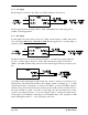
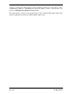
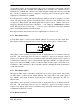
2.3.2 DC Supply
For DC supplies, the positive lead is connected to "SUP1" and the negative to "GND". The positive
side of the supply must not be connected to earth. The DC supply may be a floating supply or
negatively grounded.
+
-
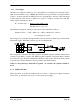
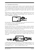
The 905 module may also be powered from an external 11 - 15 VDC battery supply without the
need for a "normal" supply connected to "SUP1". This external battery supply is connected to
"BAT+" and "GND" terminals. The positive lead of the external supply should be protected by a 2A
fuse.
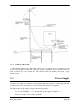
Upon failure of the normal supply, the 905 module may continue to operate for several hours from a
backup battery. The 905 module includes battery charging circuits for charging up to a 12 AHr
sealed lead acid battery. The battery is connected to the "BAT+" (positive) and "GND" (negative)
terminals. The positive lead from the battery should be protected with a 2A fuse, installed as near to
the battery terminal as possible. On return of main supply, the unit will switch back to mains
operation, and recharge the battery. To provide adequate current to recharge the backup battery,
an AC supply of 15V minimum or a DC supply of 17V minimum must be used. Typically, a 6 AHr
battery will supply the 905 for 1 - 3 days, depending on I/O loads.