
User's Manual

Chapter Three Operation
Page 9 © February 2005
Chapter Three OPERATION
3.1 Power-up and Normal Operation
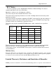
When power is initially connected to the 905U-E module, the module will perform internal
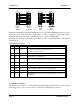
diagnostics to check its functions. The following table details the status of the indicating LEDs
on the front panel under normal operating conditions.
LED Indicator Condition Meaning
OK On Normal Operation
Radio RX GREEN flash
RED flash
Radio receiving data
Weak radio signal
Radio TX Flash Radio Transmitting
Serial RX GREEN flash
RED flash
Serial Port Receiving
CTS low
Serial TX GREEN flash Serial Port Transmitting
LINK On On when a radio communications link is
established
LINK Off Communications failure or radio link
not established
Other conditions indicating a fault are described in Chapter Six Troubleshooting.
3.2 Ethernet Data
3.2 Serial Data
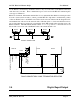
The 905U-E module provides a full-duplex RS232 serial port and half-duplex RS485 serial port.
The radio communications is half-duplex - this means that the 905U-E operates at half duplex.
Many applications use full duplex RS232 communications but do not require full duplex - the