
User's Manual


905U-E Wireless Ethernet Bridge User Manual
Man_905U-E Rev 1.0 Page 8
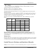
As the RS485 communication medium is shared, only one of the units on the RS485 cable may
send data at any one time. Thus communication protocols based on the RS-485 standard require
some type of arbitration.
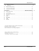
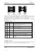
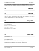
RS485 is a balanced, differential standard but it is recommended that shielded, twisted pair cable
be used to interconnect modules to reduce potential RFI. It is important to maintain the polarity
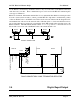
of the two RS485 wires. An RS485 network should be wired as indicated in the diagram below
and terminated at each end of the network with a 120 ohm resistor. On-board 120 ohm resistors
are provided and may be engaged by operating the single DIP switch in the end plate next to the
RS485 terminals. The DIP switch should be in the “1” or “on” position to connect the resistor. If
the module is not at one end of the RS485 cable, the switch should be off.
HOST
905U-D
HOST
RS485 CONNECTIONS
120
Ω
RS485
SUPPLY
RS232
DIP SWITCH
FOR 120Ω
120
Ω
HOST HOST
905U-E
+
-
+
-
+
-
RS485 CONNECTION USING TERMINATING RESISTOR
ETHERNET
DIO
DEFAULTS DIP SWITCH
2.4 Digital Input/Output