
User's Manual

Chapter Two Installation
Page 7 © February 2005
905U-D
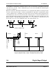
DB9
MALE
DTE HOST
DB9
FEMALE
905U-D
DB9
MALE
DCE HOST
DB9
MALE
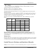
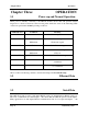
Hardware handshaking using the CTS/RTS lines is provided. The CTS/RTS lines may be used to
reflect the status of the local unit’s input buffer, or may be configured to reflect the status of
CTS/RTS lines at the remote site. The 905U-D does not support XON/XOFF.
Example cable drawings for connection to a DTE host (a PC) or another DCE host (or modem) are
detailed above.
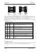
DB9 Connector Pinout
Pin Name Direction Function
1 DCD Out
Data carrier detect –
- on when link is established in controlled mode
- on always in transparent mode
2 RD Out
Transmit Data – Serial Data Output
3 TD In
Receive Data – Serial Data Input
4 DTR In
Data Terminal Ready - DTR can be configured to initiate low power
mode, or to force a link disconnection (“hang up” in controlled mode.
5 SG
Signal Ground
6 DSR Out
Data Set Ready - always high when unit is powered on.
7 RTS In
Request to Send - hardware flow control configurable
8 CTS Out
Clear to send - hardware flow control configurable
9 RI
Ring indicator - indicates another module is attempting to connect in
controlled mode.
2.4.2 RS485 Serial Port
The RS485 port provides for communication between the 905U-E unit and its host device using a
multi-drop cable. Up to 32 devices may be connected in each multi-drop network.