
User's Manual


905U-E Wireless Ethernet Bridge User Manual
Man_905U-E Rev 1.0 Page 26
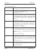
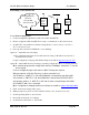
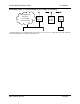
Extending a wired network
905U-E
Access
Point,
Bridge
905U-E
Client 1,
Bridge
PLC
Existing Ethernet
Network
192.168.0.0
255.255.255.0
Ethernet HUB / SWITCH
905U-E
Client 2,
Bridge
PLC
Access Point Configuration
1. Connect straight through ethernet cable between PC and 905U-E.
2. Ensure configuration PC and 905U-E are setup to communicate on the same network
3. Set 905U-E to start with factory default settings. Refer to section Setting a 905U-E to
Factory Default Settings.
4. Power up unit, and wait for LINK led to cease flashing.
Option A – Adjust PC network settings
a) Set Configuration PC network card with network setting of IP address 192.168.123.1,
netmask 255.255.255.0
b) Open configuration webpage with Internet Explorer at address http://192.168.123.123/
Option B – Adjust 905U-E network settings (assuming configuration PC is on existing network)
Open terminal program with settings with data rate 19200bps, 8 data bits, 1 stop bit
and no parity.
Connect straight through serial cable to 905U-E and power up unit.
When prompted, strike the Enter key to abort automatic boot
Set IP address of 905U-E to 192.168.0.200 with command bip 192.168.0.200
Set netmask of 905U-E to 192.168.0.200 with command bnm 255.255.255.0
Set gateway address of 905U-E to 192.168.0.1 with command bgw 192.168.0.1
Reset 905U-E with reset command.
Open configuration webpage with Internet Explorer at address http://192.168.0.200/
5. Click on Network settings menu option.
6. When prompted for password, enter default username “user” and password “user”
7. Set the Operating Mode to Access Point
8. Device Mode should be set to Bridge.
9. Set the Gateway IP address to 192.168.0.1