
User's Manual


Elpro Technologies E2-450 Radio Module Instruction Manual
Rev Version 1.0
www.cooperbussmann.com/wirelessresources
9
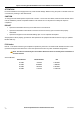
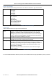
Alternate Host Interface Pin Description
5.1
Pin
Signal Description Direction
1 VSupply 13.8V regulated supply from host Input to module
2 GND Ground
3 VSupply 13.8V regulated supply from host Input to module
4 GND Ground
5 5V_CON 5V regulated supply from host Input to module
6 GND Ground
7 5V_CON 5V regulated supply from host Input to module
8 GND Ground
9 5V_CON 5V regulated supply from host Input to module
10 nR_OC Over Current Output from module
11 3.3V_CON 3.3V supply rail supplied by host Input to module
12 nEN_RADIO_PWR
Radio Power Enable Input to module
13 3.3V_CON 3.3V supply rail supplied by host Input to module
14 TXD0_7 Data Transmit Input to module
15 RXD0_7 Data Receive Output from module
16 RTS0_7 Ready to Send (When toggled, it indicates that
the radio processor should wake up.)
Input to module
17 CTS0_7 Clear to Send (When toggled, it indicates that
the host should wake up.)
Output from module
18 N.C Not connected
19 N.C Not connected
20 Test Point Not used