
User's Manual

Elpro Technologies 450U-E Wireless Ethernet Modem & Device Server User Manual
Rev Version 1.0.12-Beta7 www.cooperbussmann.com/wirelessresources 53
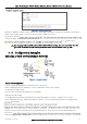
LAN B Configuration
All devices on LAN B should be configured so their Gateway IP addresses are configured with the IP address
169.254.102.54 which is the 450U-E Access Point/Router.
Access Point Configuration
Connect straight through Ethernet cable between the PC and the 450U-E.
Ensure configuration PC and 450U-E are setup to communicate on the same network
Set dipswitch to SETUP
Power up unit, and wait for OK led to cease flashing.
Adjust PC network settings
Set Configuration PC network card with network setting of IP address 192.168.0.2, Netmask 255.255.255.0
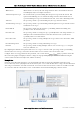
Open configuration webpage with Internet Explorer at address 192.168.0.1XX where XX is the last two digits of the
screen.
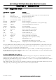
On this screen select the Transmit Power level, Transmit Data Rate, Frequency Step size and Transmit & Receive
Select Operating Mode as Access Point.
Enter a System Address (ESSID) string. And record as this will need to be exactly the same for all radios in the example.
The Radio Encryption is configured for WPA2 AES and will require an encryption key which will also need to be the same
on all radios in the example.
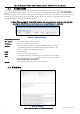
Change the IP addresses to 192.168.0.200
Leave the Subnet masks at the default 255.255.255.0
Leave the Gateway IP Address at the default 192.168.0.1 as it is not used in this example.
to
the configuration before resetting the module.
This will then display separate IP address fields for Ethernet and Wireless.
As the Access Point is now configured as a Router it will route the IP traffic from one network to another.
Change the Wireless IP address to the 169.254.102.54 which is the IP address on the Wireless network.
Set dipswitch back to RUN
Client Configuration
Perform the same configuration steps as the Access Point configuration with the following differences:
Ensure that the Radio, System Address (ESSID) and Encryption key are the same as the Access Point.
Set the Operating Mode to Client.
Because the radio network is on a different IP range change the IP addresses to 168.254.102.53
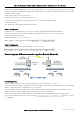
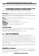
Extending range of a network with a Repeater hop
Configure units as described in example above. Place the Access Point at the remote
intermediate repeater location. Additional repeaters can be added using Wireless Distribution System (WDS) refer
section 3.12 Repeaters (WDS) Repeaters (WDS) for further details.