
User's Manual

Elpro Technologies 450U-E Wireless Ethernet Modem & Device Server User Manual
48 www.cooperbussmann.com/wirelessresources Rev Version 1.0.12-Beta7
It is recommend this Fail Safe Time be configured for a little more than twice the update time of the input that is turning it
on, that way the output will reset if it fails to receive two update messages.
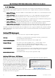
Fail-Safe State The state that the output will be set to if countdown has elapsed.
If the Failsafe state is enabled (ticked) the LED and the digital output will be turned ON.
If the Failsafe state is disabled (unticked) the LED and the digital output will be turned OFF.
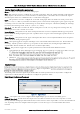
Digital Input
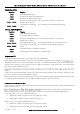
Figure 53- Input Mode
If you wish to adjust the digital input parameters see below for details.
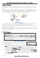
Digital Input Configuration Parameters
Name A descriptive name that can be given to the input to help with configuration, up to 30 characters including
spaces or use the default,
Debounce Time (Sec) Debounce is the time which an input must stay stable before the module decides that a change
of state has occurred. If a digital input changes (on - off) and changes again (off - on) in less than the debounce time, then
the module will ignore both changes. Default debounce time is 0.5 seconds.
I/O Register locations
There are over 5000 x 16bit general purpose registers that are available for Modbus (including the onboard Analog/Digital
Input/Output) and are shared with both Modbus Client and Server.
Along with the physical DIO status the internal I/O can be accessed by reading or writing to the following register
locations. The Register locations are structured into standard Modbus I/O types and can be accessed using the local
onboard Modbus TCP Server, Modbus serial Master or an external Modbus Master device.
The layout of the 450U-E I/O Registers are summarized in the table below. Each register is internally saved as a 16bit
unsigned integer value. A Modbus transaction may access the entire 16 bit value of any register, or alternatively the most
significant bit of a register may be accessed as a discrete value. The main use for the general purpose I/O registers is for
intermediate storage, i.e. when transferring I/O from one Modbus Slave device to another. Also provided is the status of
the onboard digital I/O, as well as the status of the wireless link and any serial or TCP connections.
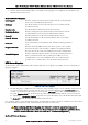
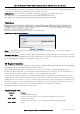
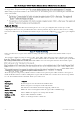
The different I/O Types and Registers are shown below.
Digital Outputs Coils
Registers
Purpose
0001
Local Digital Output Register
0021 - 0500
I/O Space for locally attached 115S expansion I/O modules. 20 registers per
module address. Max 24.
0501 - 3000
General Purpose Bit Storage Area assigned in memory for Modbus Mapping
storage.
Figure 56 Digital Input