
User's Manual

Elpro Technologies 450U-E Wireless Ethernet Modem & Device Server User Manual
Rev Version 1.0.12-Beta7 www.cooperbussmann.com/wirelessresources 47
Analog Input configuration parameters
Name Configure a descriptive name for the Analog input.
Zero This parameter is used to configure the scale of the analog input. This is the starting variable (in counts) when the
analog input is at the bottom or zero scale. Default is 8192 which equates to the number of raw counts in the register
when the input is at the zero or minimum value, i.e. 0mA on the analog input.
Span This parameters is used to configure the scale of the analog input. This is the number of counts per measured
value, i.e. 1 mA, 1 V, 1 HZ, etc.). Default is 2048 which equates to 20mA on the analog input. E.g. the register range has
a total range of 32768 counts with a total mA range of 16mA; therefore the Span is calculated by dividing the total range
in counts by the total range in mA, V, Hz, etc. (32768 / 16 = 2048)
Filter (sec) The Filter time Constant is the time the analog takes to settle on a step changed of an analog value. By
default, inputs have a time constant of 5 seconds.
Lower Setpoint This parameter is the lower control point value that is used in conjunction with the Upper Setpoint to
turn on and off the Analog Setpoint register. AI1 setpoint location is at register 10002 and VSupply setpoint is located at
register 10003.
Upper Setpoint This parameter is the upper control point value that is used in conjunction with the Lower Setpoint to
turn on and off the Analog Setpoint register.
Invert This option toggles the Setpoint control logic between the default normal and inverted state. The function does
not change, only the operation is inverted, e.g. if setpoint is on in its normal state, inverting the signal will mean the
setpoint will be off in the normal state. Default state is not inverted (not ticked)
Window This parameter toggles the Set point operation between the Default and the Windowed modes.
Default (un-ticked) - If the Analog Input is greater than the Upper Set point, the set-point status will be active (on,
Windowed
Digital Output
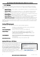
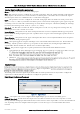
Figure 53- Input Mode
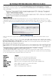
The default parameters for the digital output should suffice for normal operation however if you wish to configure the
output to have a failsafe indication you will need to configure the parameters below.
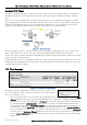
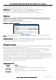
Digital Output Configuration Parameters
Name A descriptive name can be configured for the Digital Output, up to 30 characters including spaces.
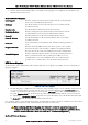
Fail-Safe Time (sec) The time before the output actives its Failsafe state if it does not receive an update or a COS
message from the sending input. If the Fail Safe Timer counts down to zero the output will be set to the ON /OFF Fail Safe
state depending on how it is configured. When an update or a COS message is received the Failsafe timer is then
restarted.
Figure 55 Digital Output