
User's Manual

Elpro Technologies 450U-E Wireless Ethernet Modem & Device Server User Manual
Rev Version 1.0.12-Beta7 www.cooperbussmann.com/wirelessresources 45
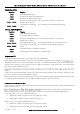
Local Register
Enter the starting onboard I/O register number that the specified Modbus Master
transaction will transfer I/O to/from.
I/O Count
Specify the number of consecutive I/O register to be transferred for the specified
transaction.
Function Code
Specify the Modbus Function Code for the transaction.
Destination Register
Enter the starting I/O register number in the destination device that the specified
Modbus Master transaction will transfer I/O to/from.
Device ID
Enter the Modbus Device ID of the destination Modbus device
Server IP Address
Specify the IP Address of the destination Modbus TCP Server for the specified
transaction.
Sever Port
Server Port number used for Modbus TCP. Default/standard port number is 502
Response Timeout
Enter the timeout (in milliseconds) to wait for a response to the specified
transaction.
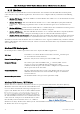
Comms Fail Register
Enter the onboard I/O Register number to store the communication status for the
specified transaction. If the register selection is a digital input register (10501), the
register will be set to 0 (off) if communications is successful and 1 (on) if there is no
connection to the server. If a general Input register is used (30501-32500) for the
Comms Fail is it will write the status and the error code which is useful for
diagnosing communication problems. I.e. 0xFFxx where xx is the Modbus
Exception Code. See Appendix D - Modbus Error Codes for more details on the
Modbus Error Codes.
Note: When entering the Local or Destination registers you do not need to enter in the full Modbus
Address, i.e. 30001 or 10001 only the I/O address is needed as the Function Code determines what
type of command is being used.
E.g. if you wish to read from Destination register 30001 you need to select Function Code 04: Read
Inputs and then enter the Destination Register of 1.
Or if you wish to read register 10501 you need to select Function Code 02: Read Discretes and then
enter the Destination Register of 501.
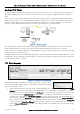
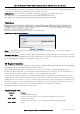
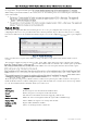
Modbus TCP to RTU Conversion
The Modbus TCP to RTU Gateway allows an Ethernet Modbus/TCP
Client (Master) to communicate with a serial Modbus RTU Slave. The
450U-E makes this possible by internally performing the necessary
protocol conversion. The conversion is always performed by the
450U-E which is directly connected to the Modbus serial device (i.e.
only this module needs to have Modbus TCP to RTU Gateway
enabled).
The above example demonstrates how a Modbus/TCP Client (Master) can connect to one or more Modbus RTU (i.e.
serial) Slaves. In this example the 450U-E Access Point is configured with the connected serial port configured for
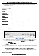
When enabled, the gateway converts the Modbus/TCP query into Modbus RTU and forwards
theme out the serial port to the Slave. When the serial device response the query arrives from the Slave, it is converted
back into a Modbus/TCP response and forwarded via the network to the Modbus/TCP Master. If no response was
received serially by the 450U-E within the configured Response Timeout, the 450U-E will initiate a number of retries
specified by the configured Maximum Request Retries.
The Modbus TCP to RTU Gateway may be configured to operate on either the RS-232 or RS-485 port.
Figure 51 - Modbus TCP-RTU