
User's Manual

Elpro Technologies 450U-E Wireless Ethernet Modem & Device Server User Manual
Rev Version 1.0.12-Beta7 www.cooperbussmann.com/wirelessresources 43
Modbus TCP Client
The Modbus TCP Client/RTU Master enables the 450U-E to connect to one or more Modbus TCP Servers/RTU Slaves.
All Modbus Mappings are directed to/from the onboard I/O registers depending on configuration which is described
below.
There are two separate mapping tables, one for TCP Clients mappings and one for RTU Master Mappings. The RTU
Master Mappings table is used for communications to Modbus Slave devices connected on the RS232 or RS485 ports
and the TCP Client Mappings table is used for communications with TCP Servers via the Ethernet port. Each of the
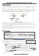
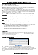
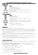
mapping scenarios will be explained below based on the system in Figure 48 Modbus Example
The system in Figure 48 above shows that site B is a Modbus TCP Client and will poll the TCP server at Unit C via the
Wireless Ethernet interface to get the status of the on board DIO which will then be reflected on its own DIO.
Site B is also setup as a Modbus RTU Master which will poll 8 x single bit registers from Modbus serial device A and then
transfers the values to internal registers.
Enabling the Modbus TCP Server within unit B will provide a register location for the previously polled values to be stored.
It will also allow an external Modbus TCP Client (DCS or Scada) to monitor the stored I/O values from units A & C via the
extended wired or wireless networks.
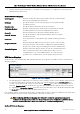
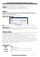
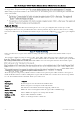
TCP Client Mappings
The Modbus TCP Client / RTU Master is enabled and is using a 500msec scan
rate, meaning that there will be a 500msec delay between each of the
mappings
directed at any Modbus server.
This TCP mapping transfers the status of the onboard digital input at C to the onboard digital output at B.
Local
Register
(1) specifies the register for the onboard digital output at B. This register is configured with 1 which is
the register used to turn on the Digital Output.
I/O Count
(1) specifies that only one I/O point is being transferred
(i.e. the single digital I/O).
Function Code
02: Read Discretes specifies the standard Modbus function code to
read discrete (i.e. digital) inputs.
Destination Register
(1) specifies the register for the onboard digital input at the
Server IP address (unit C).
Device ID (
3) is the ID of the onboard Modbus TCP Server at C.
Server IP Address
(192.168.0.200) is the IP address of unit C which is the Modbus TCP Server we are reading from.
Server Port
is the TCP port used.
Response Timeout
(1000ms) specifies that unit C must respond to this message within
1000ms.
Comm Fail Register
(0) specifies the local register where the communications status for this mapping
will be stored.
Figure 48 Modbus Example
Figure 49 - Site B Modbus TCP Mappings