
User's Manual
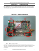


Elpro Technologies E2-450 Radio Module Instruction Manual
10 www.cooperbussmann.com/wirelessresources Rev Version
1.0
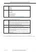
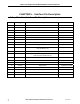
CHAPTER 5 - Interface Pin Description
5.0 Main Host Interface Pin Description
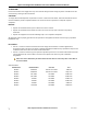
Pin Signal Description Direction
1 GND Ground
2 5V_RADIO 5V supply rail supplied by host Input to module
3 GND Ground
4 5V_RADIO 5V supply rail supplied by host Input to module
5 GND Ground
6 VSUP_CON Main DC input power supply rail of the host (9-30V) Input to module
7 GND Ground
8 VSUP_CON Main DC input power supply rail of the host (9-30V) Input to module
9 3.3V_RADIO 3.3V supply rail supplied by host Input to module
10 CTS0_7 Clear to send (When toggled, it indicates that the
host should wake up.)
Output from module
11 3.3V_RADIO 3.3V supply rail supplied by host Input to module
12 RTS0_7 Ready to Send (When toggled, it indicates that the
radio processor should wake up.)
Input to module
13 BRX Not used
14 TXD0_7 Data Transmit Input to module
15 BTX Not used
16 RXD0_7 Data Receive Output from module
17 _SHDN Radio Shutdown Input to module
18 AUX1 Not used
19 nR_OC Over Current Output from module
20 GND Ground