
User's Manual


Elpro Technologies 450U-E Wireless Ethernet Modem & Device Server User Manual
46 www.cooperbussmann.com/wirelessresources Rev Version 1.4.0
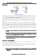
Enabling the Modbus TCP Server within Unit B provides a register location for the polled values from Unit C to be stored.
It will also allow an external Modbus TCP Client (DCS or Scada) to monitor the stored I/O values from units A & C.
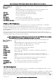
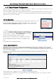
Firstly the Modbus TCP Client must be enabled and a suitable scan rate be
selected, the default time will be 1000msec meaning that there will be a 1 second
delay between the Client mappings directed at any Modbus server.
Next the mappings need to configured, see below for the explanation.
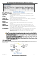
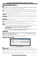
The Example TCP mapping in Figure 53 - Unit B Modbus TCP Mappings is configured to transfers the status of the
onboard digital input at Unit C (Device ID#3) to the onboard digital output at Unit B.
Local Register
(1) specifies the register for the onboard digital output at B. This register is configured
with 1 which is the register used to turn on the Digital Output.
I/O Count
(1) specifies that only one I/O point is being transferred (i.e. the single digital I/O).
Function Code
(02: Read Discretes) specifies the standard Modbus function code to read discrete (i.e.
digital) inputs.
Destination Register
(1) specifies the register for the onboard digital input (1) As the Function Code is a
Read Discrete, this indicates that the Destination register will be in the range 10XXX range and so we
only need to put in the register location and not the function designator (10XXX).
Device ID (
3) is the ID of the onboard Modbus TCP Server at C.
Server IP Address
(192.168.0.200) is the IP address of unit C which is the Modbus TCP Server we are
reading from.
Server Port
is the TCP port used.
Response Timeout
(1000ms) specifies that unit C must respond to this message within 1000ms.
Comm Fail Register
(0) specifies the local register where the communications status for this mapping
will be stored.
Modbus TCP Client functionality allows a maximum of 100 mappings to be configured and a maximum of 24 different
Modbus TCP Servers.
Figure 53 - Unit B Modbus TCP Mappings
Figure 52 - TCP Client