
User's Manual


Elpro Technologies 450U-E Wireless Ethernet Modem & Device Server User Manual
40 www.cooperbussmann.com/wirelessresources Rev Version 1.4.0
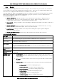
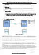
The above network diagram illustrates a situation where routing rules may need to be configured. In this example, the
450U-E clients need only specify the Access Point as their default gateway (i.e. they require no routing rules to be
configured). However, for the Access Point to be able to deliver traffic to LAN B and LAN C it needs to have routing rules
configured that specify the respective 450U-E client/routers as next-hop routers (i.e. gateways) to networks B and C.
Note that devices on LAN A should specify the 450U-E Access Point as their default gateway. An
alternative to adding routing rules to the 450U-E in this example would be for each device on LAN A
that needs to communicate with LANs B and C to have independent routing rules specifying the
450U-E clients at B and C as gateways to those networks.
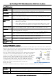
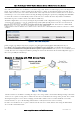
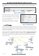
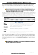
The routing rules for the Access Point in the above example are shown below in Figure 46. The first entry shows the route
to LAN B. The gateway for the route to LAN B is configured as the wireless IP address of the 450U-E client connected to
LAN B. The destination for the route is configured as the
network
address of LAN B. Because the
host
id of the
destination IP address is 0, it specifies a network address. Consequently, any traffic received at the Access Point with
destination IP address 169.254.109.x (where x is any host id) will be forwarded to the 450U-E at LAN B.
Devices on LAN B & LAN C that needs to send messages back to LAN A will need to have their Gateway addresses
directed to the 450U-E on their respected networks. I.e. a LAN B device needs to send data back to LAN A. The
Gateway address will need to be configured as 169.254.109.40 as this is the IP address of the wired side of the LAN B
450U-E. Any message coming in with a 192.168.0.X IP address will be directed across the wireless interface to LAN A.
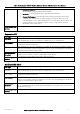
The Routing Rules configuration page can be accessed any of the configuration web
pages. Up to 30 routing rules may be added to each 450U-E. The table below summarizes the configurable parameters
of a routing rule.
Note: Entering dedicated Ethernet Routes can also be added to the wired Ethernet LAN in place of
generating / adding routing rules into the modems.
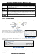
Name
A name that describes the routing rule (Max 32 characters).
Destination
The destination network (or host) IP address (to specify a network address set the host
address to 0. i.e. for an IP address 192.168.0.0 with Netmask 255.255.255.0 would
specify a destination network, while 192.168.0.16 specifies a destination host).
Subnet Mask
The subnet mask for the destination network.
Gateway
The IP address of the next-hop router for the specified destination.
Enabled
Check this box to enable the rule. You can uncheck the box to disable a routing rule
without needing to re-enter the information at a later time.
Figure 46 - Routing Rules @ AP