
User's Manual


Elpro Technologies 450U-E Wireless Ethernet Modem & Device Server User Manual
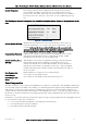
Rev Version 1.4.0 www.cooperbussmann.com/wirelessresources 35
communicate with the serial device.
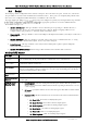
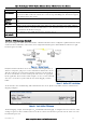
Flow Control
Flow Control is used by some serial devices to regulate the flow of data by turning on/off flags that
are used to tell the connected serial devices to start or stop transmitting data. The RS232 supports
CTC/RTS hardware flow control.
Response
Timeout
This is the time the TCP/RTU Converter waits for a response from the slave before sending the next
poll.
TCP Port
Fixed to 502.
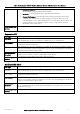
Device ID
Address of the onboard Modbus RTU Slave/TCP Server. This is the Address that will be polled by
the Modbus Master / TCP Client. Default address is 255 and is fixed on this screen; however it can
be modified on the Modbus TCP page.
Save Changes
and Activate
Save changes to non-volatile memory and activate the process
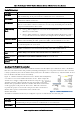
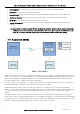
Modbus RTU Mappings Example
The system in Figure 36 below shows that Unit B is a Modbus RTU Master that is configured to poll the RTU Slave Device
at Unit A via the serial interface and read the status of eight onboard I/O registers which will then be reflected to eight
local I/O registers at Unit B.
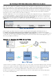
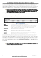
Firstly the Modbus RTU Master needs to be enabled on the dropdown list of
whatever serial port is going to be used to communicate with the Slave device.
Then the serial Data rate, Data format and Flow control need to match that of
the device and then the Scan rate and Response time need to be appropriate
for the application. The Scan Rate in this example is set for 1 second and it will
also wait 1 second for a response from the slave before flagging a Comms
Failure.
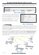
As the module is also communicating with a Modbus RTU slave device (Device #5) it will need to have an RTU Master
Mapping configured.
The RTU Mapping example shown in Figure 38 Unit B Modbus RTU Mapping is configured to read 8 x Discrete values
starting at register 501 from a Modbus Slave Device ID #5 connected to the RS232 port and store the values at its own
local internal register 501.
Figure 38 Unit B Modbus RTU Mapping
Figure 36 Modbus Example
Figure 37 - Modbus RTU Serial Settings