
User's Manual


Elpro Technologies 450U-E Wireless Ethernet Modem & Device Server User Manual
32 www.cooperbussmann.com/wirelessresources Rev Version 1.4.0
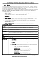
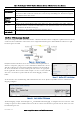
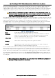
Serial 3.8
The Serial page allows configuration of the onboard serial ports. The 450U-E has two ports, one RS-232, and one RS-
485 port which are used for serial communications with other devices. These ports are completely independent of the
other and can be configured for different functions even utilised at the same time.
The 450U-E offers five different and each port is configured separately by selecting from the drop down list
the appropriate parameters associated with this function.
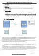
The Available Port Types are:
Modbus RTU Master This type should be selected when the port is operating as a Modbus Master, i.e.
Modbus RTU slave devices are connected directly to the serial port. Modbus mappings will need to be
configured in the table provided, see below for details on how this is done.
Expansion I/O This type should be selected when Elpro Serial Expansion modules (115S-XX) are connected to
the modem.
Modbus RTU Slave This type should be used if the port is being used as a Modbus RTU slave, i.e. being
connected to from a Modbus Master (DCS, Scada, etc.) via the serial port.
Serial Gateway This type should be selected if you wish to allow point to point or point to multipoint
transparent serial data transfers.
Modbus TCP/RTU Converter This Port Type allows Modbus TCP to Modbus RTU conversion.
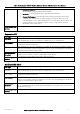
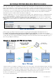
Modbus RTU Master
Port Type
Select Modbus RTU Master from the drop down list.
Data Rate
Serial Data Rate will need to be configured to match that of the serial device that is connected
and communicating via the port. Baud rates available from 110 to 230400 baud.
Data Format
Serial Data Format defines the number of data bits, parity and start/stop bits that is used to
communicate with the serial device.
Flow Control
Flow Control is used by some serial devices to regulate the flow of data by turning on/off flags
that are used to tell the connected serial devices to start or stop transmitting data. The RS232
supports CTC/RTS hardware flow control.
Modbus Scan
Rate
Configures the frequency with which the Slave Device will be polled. Default is 100msec.
Modbus Response
Timeout
This is the time the RTU Master / TCP Client waits for a response from the slave from the
previous poll.
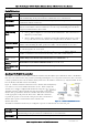
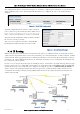
Mapping Master
Mapping Table
Local Register Enter the starting onboard I/O register number that the specified
Modbus Master transaction will transfer I/O to/from depending on whether it is a read or
a write mapping.
I/O count Specify the number of consecutive I/O register that will be transferred in the
mapping.
Function Code Modbus Function Code used for the transaction. Standard Function
codes are:
o 01: Read Coil - Read from a Coil (Output) register.
o 02: Read Discretes - Read from a Discrete Input register.
o 03: Read Registers - Read from an Analog Output register.
o 04: Read Inputs - Read from an Analog Input register.
o 15: Write Coils- Write to a Coil (output) register.
o 16: Write Registers - Write to an Analog Output register.