
User's Manual


Elpro Technologies 450U-E Wireless Ethernet Modem & Device Server User Manual
26 www.cooperbussmann.com/wirelessresources Rev Version 1.4.0
Note: If making changes to a remote module via the radio link make sure all changes are compliant
and accurate before Changes and R top
the radio link from working and will require a hard wire connection to change back.
Care should be tken when connecting the modem to existing Networks - When configured as a
Bridge (default), all broadcast messages appearing at its wired Ethernet port will be transmitted over
the radio. As the modem has a low data throughput any unnecessary traffic being sent over the radio
could compromise the reliability of the wireless link. In many cases, the intended recipient of the
broadcast traffic that is heard on the Ethernet port does not lie at the opposite end of a radio link.
Therefore it is recommended that the radios be configured with some basic filtering or be configured
as a routing network to limit unnecessary broadcast traffic being sent over the radio. Refer to Section
3.11 Filtering
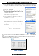
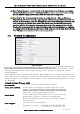
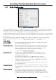
Network Configuration 3.5
. The Network Configuration page
allows configuration of parameters related to the wired and wireless Ethernet interfaces. In general, IP address selection
will be dependent upon the connected wired Ethernet device(s) before connecting to an existing LAN consult the
network administrator.
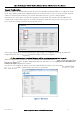
Default configuration of the module will be Client and Bridge. When in Bridged Mode the modules wired and wireless IP
address will be the same, meaning only one IP Address is required. If the Device Mode is changed to Router the page will
display two IP addresses, one for Ethernet and one for Wireless. For more information on Bridging Networks see section
3.10 IP Routing
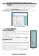
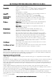
Network Settings Webpage Fields
Operating Mode
Used to select Access Point, Client. Default is set to Client.
System Address (ESSID)
A 450U-E wireless network comprises modules with the same "system
with each other. The system address is a text string 1 to 31 characters in
length. Select a text string which identifies your system.
Desired BSSID
To force a client/station to always connect to the same Access Point enter
the MAC address of that Access Point in the Desired BSSID field
(Note that the ESSID of the Access Point must also match the configured
ESSID of the client).
Radio Encryption
Select the desired radio Encryption level.
Encryption key, passphrase, etc.
Figure 28 Network