
User's Manual

Elpro Technologies 450U-E Wireless Ethernet Modem & Device Server User Manual
Rev Version 1.4.0 www.cooperbussmann.com/wirelessresources 19
LED Indication
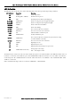
The following table details the status of the indicating LEDs on the front panel for all operating conditions.
LED Indicator
Condition
Meaning
OK
GREEN
Normal Operation
OK
Flashing RED / GREEN
Module Boot Sequence
OK
RED
Default Quick start Mode (Unconfigured)
Radio RX
GREEN flash
Radio receiving data (Good Signal Strength)
Radio RX
RED flash
Radio receiving data (Low Signal strength)
TX/LINK
GREEN
Radio Connection Established
TX/LINK
RED
Radio Transmitting
RS-232
GREEN flash
Data sent from RS-232 Serial Port
RS-232
RED flash
Data received to RS-232 Serial Port
LAN
ON
Link Established on Ethernet port
LAN
ORANGE flash
Activity on Ethernet port.
RS-485
GREEN flash
Data sent from RS-485 Serial Port. If expansion I/O is being
used this will flash constantly
RS-485
RED flash
Data received to RS-485 Serial Port
IO
GREEN
Digital Input is On.
IO
RED
Digital Output is active
IO
OFF
Digital Output OFF and Input is open circuit.
IO
GREEN different intensity
Analog input current loop.
dim = 4mA, bright= 20mA
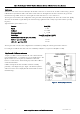
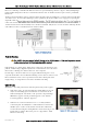
The Ethernet RJ45 connector on the end of the module incorporates two indication LEDs. The LINK LED which comes on
to indicate a connection on the Ethernet port, and it will blink OFF briefly when activity is detected, similar to the LAN Led
on the front panel. The 100MB LED indicates that the LAN connection is at 100 MBit/Sec. The 100MB LED will be off for
10MB/Sec connection.
Other conditions indicating a fault are described in CHAPTER 4 - DIAGNOSTICS.