
User's Manual

Elpro Technologies 450U-E Wireless Ethernet Modem & Device Server User Manual
16 www.cooperbussmann.com/wirelessresources Rev Version 1.4.0
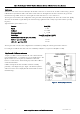
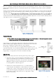
Input/Output Connections 2.4
The 450U-E has a single physical on-board I/O channel that can be configured as either a Digital or an Analog via the web
interface. The Digital channel can act as an input or an output. It can be monitored, set remotely, or alternatively used an
output for a communications alarm status. If more I/O is required, you can add 115S serial expansion I/O modules via the
RS232 or RS485 ports. See section 3.13 for more details on this.
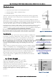
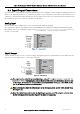
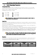
Analog Input
The I/O channel can be configured to accept a 0-20mA current sinking analog input.
The current source must be externally powered and the ADIO must be configured for Analog Input rather than Digital
Input/Output. This can be configured by going to the / screens see
section 3.13 for details.
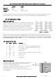
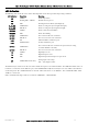
Digital Output
The I/O channel can also be used as a discrete output. The digital output uses a FET transistor rated at 30VDC 500 mA,
and can be used to switch a load, i.e. relay coil or contactor.
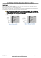
The output can be activated by manually writing a value of re
by utilising the onboard Modbus TCP Server or Serial Modbus Master to turn
on the output. It could also be accessed from an external Modbus Server, i.e. a PLC, DCS, Scada,
etc. via the Ethernet network or Serial interface.
When activating the output the I/O indication on the front panel of the module will be lit RED when
the output is on.
Note: The Digital Output will override the Digital Input operation, i.e. if the output is activated while
the DIO is being read the indication will show the input as being on (1).
Figure 18 - DIO Output
Figure 17 - Analog Input