
User's Manual

Elpro Technologies 450U-E Wireless Ethernet Modem & Device Server User Manual
Rev Version 1.4.0 www.cooperbussmann.com/wirelessresources 15
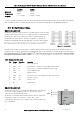
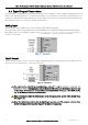
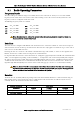
RS485 is a multi-drop communication link or bus that can span relatively large distances (up to 1.2Km (4000ft)) using a
balanced differential paired cable. It is recommended that the cable be shielded or twisted pair to reduce potential RF
Interference.
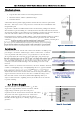
An RS485 network should be wired as indicated in the diagram below and terminated at each end of the network with a
120-ohm resistor. An on-board terminating resistor is provided in the modem which can be engaged by operating the
single DIP switch on
connect the resistor. If the RS485 device that the modem is being connected to does not have a termination switch a
120ohm resistor must be fitted manually across the RS485 terminals. Only devices at each end of the multi-drop RS485
cable will need to have a termination resistor enabled or fitted.
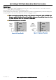
Failsafe Biasing
The 450U-E does not support Failsafe Biasing on the RS485 unless a 115S serial expansion module
is also connected and has its termination switch enabled.
Failsafe Biasing is a simple voltage divider that is connected to the RS485 bus and
pulls the terminal voltages (high or low) when the communication state is idle rather
than be left at a floating state which could cause data corruption.
If connecting a serial device that does not support Failsafe Biasing and a 115S
expansion I/O module is also not fitted then Biasing resistors must be wired to each
RS485 terminal to ensure correct operation. Resistor values will depend on the
Supply voltage; see diagram for resistor value calculation and wiring.
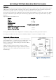
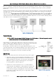
USB Ports
Module has a two USB ports housed under the plastic bung on the top plate.
USB A Host port is used for upgrading the module firmware and can
only be used for full upgrades. Patches files are not loaded via the
USB but through the web interface. The procedures for performing a
full firmware upgrade and the patch file upgrade can be found in
Section Appendix A - Firmware Upgrades
USB B Device connector which is used as a secondary Ethernet
connection point. Essentially this is a USB to Ethernet converter that
will allow you to connect to the modules web interface without the
need for disconnecting the existing Ethernet connection or the need to
install a hub or switch to allow more ports. See Appendix B - USB
Ethernet connection
Figure 15 -Multidrop Serial
Figure 16 - USB connections