
User's Manual

Elpro Technologies 450U-E Wireless Ethernet Modem & Device Server User Manual
14 www.cooperbussmann.com/wirelessresources Rev Version 1.4.0
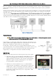
A Ground Terminal is provided on the back of the module. This Terminal should be connected to the Main Ground point
of the installation in order to provide efficient surge protection for the module (refer to the Installation Diagram)
Serial Connections 2.3
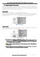
RS232 Serial Port
The RS232 serial port on the 450U-E is a 9 pin DB9 female connector which
provides connection for host devices as well as providing a connection point
for diagnostics, field testing and factory testing. Communication is via
standard RS232 signals and the 450U-E is configured as a DCE device.
Hardware handshaking using the CTS/RTS lines is provided. The CTS/RTS
. The
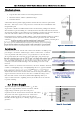
Example cable drawings for connecting to a DTE host (PC) or another DCE device (modem) are detailed in Figure 13 -
Serial Cable. A General rule of thumb for determining if the device is DCE or DTE is to look at the DB9 Connector and if
through cable and works the device is a DCE.
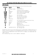
DB9 Connector Pin outs
Pin
Name
Direction
Function
1
DCD
Out
Data carrier detect
2
RXD
Out
Transmit Data Serial Data Output (from DCE to DTE)
3
TXD
In
Receive Data Serial Data Input (from DTE to DCE)
4
DTR
In
Data Terminal Ready
5
GND
Signal Ground
6
DSR
Out
Data Set Ready - always high when unit is powered on.
7
RTS
In
Request to Send
8
CTS
Out
Clear to send
9
RI
Ring indicator
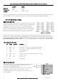
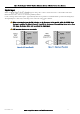
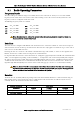
RS485 Serial Port
The RS485 port provides a communication link from the 450U-E unit to
a host device using a multi-drop cable. Up to 32 devices may be
connected in each multi-drop network.
As the RS485 communication medium is shared, only one of the units
on the RS485 cable may send data at any one time. Thus,
communication protocols based on the RS-485 standard require some
type of arbitration.
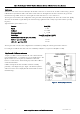
13.8VDC
24VDC
Quiescent
120mA
70mA
TX @500mW
400mA
220mA
TX @ 5W
1.2 - 1.5Amps
550mA - 650mA
Figure 13 - Serial Cable
Figure 14 - RS485