
User's Manual

Elpro Technologies 450U-E Wireless Ethernet Modem & Device Server User Manual
Rev Version 1.4.0 www.cooperbussmann.com/wirelessresources 13
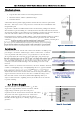
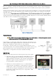
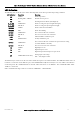
Directional antennas.
Directional antennas can be
Yagi antenna with a main beam and orthogonal elements.
Directional radome, which is cylindrical in shape.
Parabolic antenna.
A directional antenna provides high gain in the forward direction, but lower gain in other
directions. This may be used to compensate for coaxial cable loss for installations with
marginal radio path.
Yagi antennas should be installed with the main beam horizontal, pointing in the forward
direction. If the Yagi is transmitting to a vertically mounted omni-directional antenna, then the
Yagi elements should be vertical. If the Yagi is transmitting to another Yagi, then the elements at
each end of the wireless link need to in the same plane (horizontal or vertical).
Directional radomes should be installed with the central beam horizontal and must be pointed
exactly in the direction of transmission to benefit from the gain of the antenna. Parabolic
antennas s , with the parabolic grid at
Installation tips
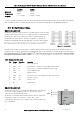
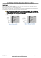
Connections between the antenna and coaxial cable should be carefully taped to
prevent ingress of moisture. Moisture ingress in the coaxial cable is a common
cause for problems with radio systems, as it greatly increases the radio losses.
We recommend that the connection be taped, firstly with a layer of PVC Tape,
PVC UV Stabilized insulating tape. The first layer of tape allows the joint to be
easily inspected when trouble shooting as the vulcanizing seal can be easily
removed.
Where antennas are mounted on elevated masts, the masts should be effectively
earthed to avoid lightning surges. For high lightning risk areas, approved ELPRO
-SMA- -N-
should be fitted between the module and the antenna. If using non ELPRO surge
suppression devices then the devices must have a 'TURN ON' voltage of less
than 90V. If the antenna is not already shielded from lightning strike by an
adjacent earthed structure, a lightning rod may be installed above the antenna
to provide shielding.
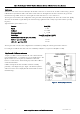
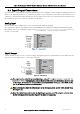
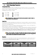
Power Supply 2.2
The 450U-E module can be powered from a 9 30 VDC
supply. The supply should be rated in accordance with the
Supply voltage and Radio power level. The power
requirements for the 450U-E unit are shown in the table below.
The positive side of the supply must not be connected to
earth. The supply negative is connected to the unit case
internally. The DC supply may be a floating supply or negatively
grounded.
Figure 10 Directional Antenna
Figure 12 - Power Supply
Figure 11 - Vulcanizing Tape