
User's Manual

Elpro Technologies 450U-E Wireless Ethernet Modem & Device Server User Manual
12 www.cooperbussmann.com/wirelessresources Rev Version 1.4.0
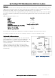
Antennas
Antennas can be either connected directly to the module connectors or connected via 50 ohm coaxial cable (e.g. RG58
Cellfoil or RG213) terminated with a male SMA coaxial connector. The higher the antenna is mounted, the greater the
transmission range will be, however as the length of coaxial cable increases so do cable losses.
The net gain of an antenna/cable configuration is the gain of the antenna (in dBi) less the loss in the coaxial cable (in dB).
The 450U-E maximum net gain will depend on the licensing regulation for the country of operation and the operating
frequency
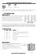
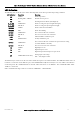
Typical antennas gains and losses are:
Antenna
Gain (dBi)
Dipole
2 dBi
Collinear
5 or 8 dBi
Directional (Yagi)
6 15 dBi
Cable Type
Loss (dB per 30 m / 100 ft)
RG58 Cellfoil Cable kits (3m,10m, 20m)
-1dB, -2.5dB, -4.8 dB
RG213 - per 10m (33ft)
-1.8 dB
LDF4-50 per 10m (33ft)
-0.5 dB
The net gain of the antenna/cable configuration is determined by adding the antenna gain and the cable loss.
For example, an 8dBi antenna with 10 meters of Cellfoil (-2.5dB) has a net gain of 5.5dB (8dB 2.5dB).
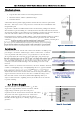
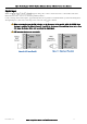
Dipole and Collinear antennas
A dipole or collinear antenna transmits the same amount of radio
power in all directions - as such that are easy to install and use. The
dipole antenna does not require any additional coaxial cable;
however a cable must be added if using any of the other collinear
or directional antennas.
Collinear and dipole antennas should be mounted vertically,
preferably 1 wavelength away (see Figure 9 for distances) from a
wall or mast and at least 3ft (1m) from the radio module to obtain
maximum range.
Figure 9 Collinear/Dipole Antenna