
User's Manual

Elpas Wireless Magnetic Contact – Installation Guide
www.elpas.com
Page 2 of 4
V3/April 2013
Aux Inputs Interface
The Magnetic Contact contains aux input terminals for
connecting two analog alert monitoring inputs.
Tamper Switch
The Magnetic Contact contains a spring loaded tamper switch
that when pressed, generates a ‘State’ message that is useful for
registering the monitoring point in the host application
Once registered, the tamper switch can also be used as an input
trigger for a device supervision tamper alert indicating non-
authorized attempts to remove the device’s cover.
Power
The Magnetic Contact derives its power from one CR2430 type
lithium battery (factory supplied) or alternatively from a single
1/2AA battery.
IMPORTANT: The Wireless Input Module as well as all the input devices
to be monitored should be powered down when wiring in order to prevent
accidental shorts/spikes to cause damage to any of the devices.
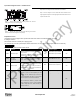
Supported Event Transmissions
The Magnetic Contact can transmit state changes from up to two dry
contact inputs (as a button press event message) to the host RTLS server.
Input 1 – Button 1 Event
Input 2 – Button 2 Event
The Magnetic Contact can also transmit a state change from the tamper
switch (as a motion event message) indicating a non-authorized attempt to
remove the module’s cover.
Tamper Switch – Motion Event
Note: Whenever a state change is detected the input module
automatically transmits 4 RF event messages 400ms apart with each
transmission about 2ms in duration).
Status Indicator
The Magnetic Contact has a Red Status LED that flashes
once/second signaling either a low voltage condition or that the
device is transmitting.
Lithium Battery Installation (supplied with device)
Before inserting the CR2430 type lithium battery into the
module’s battery holder, confirm that the holes of the battery
Isolator are aligned with the contact pins. Then ensure that the
positive (+) side of the battery faces the PCB.
IMPORTANT: Inserting the 3.6V/1.2Ah battery improperly into
the battery clip may cause damage to the Magnetic Contact.
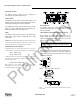
Installation Mounting
Attach the Magnetic Contact to the fixed frame and the magnet to
the movable part (door or window), as shown below. Make sure
that the magnet is located not more than 6mm (0.25 in) from the
transmitter’s marked side .
Step 1: Remove the case closure screw
Step 2: Remove the unit’s cover
Step 3: Flex out the circuit board retainer and detach the circuit board
from the base.
Preliminary