
User's Manual


Page 1 of 3
V2 - May 11
www.visonictech.com
Elpas Proximity BUS Reader
P/N: 5-LFA00125
Wiring Guide
Introduction
This wiring & installation guide provides basic instructions for common Proximity BUS Reader installation scenarios.
CAUTION! It is important that you read, understand, and follow the instructions in this document. If you have questions, call your local VT support representative.
Product Description
T
he Elpas Proximity BUS Reader is a 125KHz, EM4100
c
ompatible; indoor/outdoor surface mounted proximity reader.
T
he
r
eader features low power consumption, high reliability,
a
nd consistent read ranges (up to 10cm /4 inches), regardless
o
f card or tag.
Designed for harsh indoor/outdoor environments, the reader’s
solid state electronics is housed in an epoxy potted, IP-67
rated, weatherproof thermoplastic casing that ensures years of
maintenance free deployments.
The Proximity BUS Reader contains an onboard I/O that
enables the monitoring of one alarm sensor and control of one
digital open-collector output. The proximity reader also includes
a 2m/6.5ft long RS-485 power/data cable for interfacing to a
Elpas BUS Master (a RF IP Reader or an ELC Controller) via a
RS-485 Junction Box (P/N:5-JBA00485).
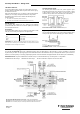
Note: An Elpas RS-485 BUS may contain up to fifteen Elpas BUS
d
evices (such as RF or IR Readers, Elpas Display Panels, LF Exciters,
o
r other Proximit
y
BUS Readers) which are wired together using Elpas
RS-485 Junction Boxes.
LF Proximity BUS Reader - Network Topology
Mounting Considerations
The Proximity BUS Reader should be wall mounted, adjacent to
the opening side of the door (outside of the protected area), at a
height of approximately 1.2m/4ft above the floor
Note: When installing Proximity BUS Readers on adjacent doors,
make certain that the minimum distance between readers is at
least 60cm/2.0ft to ensure proper operation.
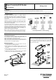
Mounting Procedure
1. Insert a screwdriver into the recess at the bottom of the case,
and separate the cover from the reader.
2. Place the base on the installation surface, mark two screw
holes, drill the holes, and insert the supplied plastic anchors, if
necessary.
3. Fasten the base to the mounting surface, using the two #6 Tap
screws supplied with the reader.
4. Replace the reader’s cover, ensuring that the cover is aligned
with the reader. This enables the LED to be visible.
Note: Do not install the Proximity BUS Reader directly onto a metal
surface, since can significantly decrease the effective read range of
the device. If you have to mount the reader onto a metal surface,
insert a RDR-BACK (P/N: 3-6317-0) between the device’s reader
base and the metal surface.