
User's Manual
Asset Tracking Tag – User Guide
Page 2 of 3
ETC03N01
Event Transmission
The Asset Tracking Tag has Button Press and Tamper inputs;
designated B1 and B2 respectively:
B1 – Monitors press/ release button activity
B2 – Monitors tamper functionality
For Tamper:
The Tracking Tag reports the state of the tamper sensor on B2. When
Tamper is detected (detached), B2=1. W hen attached, B2=0. An
EVENT message is transmitted when there is a change from attached
to detached or vice versa. When there is a change from attached to
detached (i.e. tampering), then there is a transmission of EVENT of 4
messages, 500 ms apart and B2=1. When attached, there is a
transmission of EVENT of 4 messages, 500 ms apart and B2=0.
In the steady state, the B2 bit provides the status of the tamper sensor
(if the equipment tag stays attached, B2=0, if stays detached, B2=1).
For Button Press / Release:
After button press, 4 messages are transmitted (each message about
2ms in duration), 500 ms apart, with B1=1. When the button is
released, B1=0.
An additional 4 messages (each message about 2ms in duration) are
transmitted 400 ms apart. In the steady state (no button press / button
release) B1=0.
Event Transmission in LF Zone
LF Response Time: The onboard LF receiver activates every 0.6 sec
to check if the tag is in a LF zone. Reciever is activated every 15
seconds when tag is stationary.
Transmission Rate: Continuous bursts of 4 IR/RF transmissions
(each transmission about 2ms in duration), at 0.4 second intervals.
Continues at 2 second interval while in LF field. Additional burst of 4
messages are transmitted when tag exits LF field.
Battery Replacement
1. Suspend usage of the Tracking Tag using the EIRIS
software.
2. Remove the tag from the mounting bracket using a small
flat-head screwdriver to release the clip that holds the tag in
place (Para 3, Figure 5).
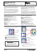
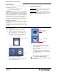
3. Unscrew the 4 screws situated at the back of the tag and
remove the back cover from the (Figures 1 and 2).
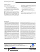
4. Carefully slide the battery out from under the battery holder
to reveal the battery isolator (Figure 3).
5. Before inserting a new battery into place, position the
battery Isolator such that the holes are aligned with the
contact pins (Figure 3).
6. Replace the battery ensuring that the positive (+) side of the
battery faces the PCB.
7. Close the back cover such that the screw holes are
correctly aligned. Tighten the 4 screws snugly into place
(toqued between 25-28 cN.m). Do not over-tightenas this
may strip the case threads.
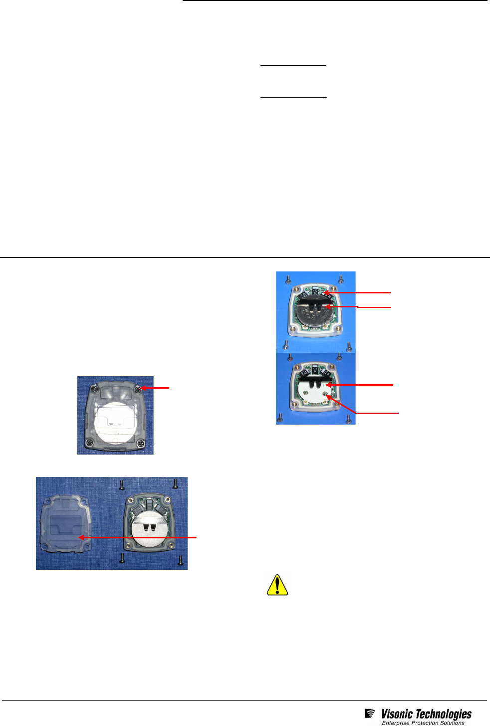
Elpas Tracking Tags require activation before use.
To activate : Press and hold the button for
5 seconds. Upon activation the LED blinks, indicating
transmission.
Back Cover Screw
Battery Holder
Battery
Battery Isolator
Contact pin
Back Cover
Figure 1: Tag (showing screws)
Figure 2: Tag (back cover removed)
Figure 3: View of Battery Removed