
User's Manual
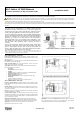
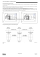
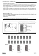
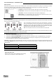
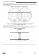
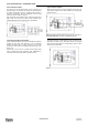
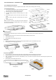
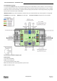
Table Of Contents

ALC LF BUS Beacon – Installation Guide
www.elpas.com
Page 7 of 12
V2/Dec 2014
ALC LF BUS Beacon Enclosure
The ALC LF BUS Beacon enclosure is comprised of three parts: a front cover, a PCB tray, and a rear cover.
To Assemble the Enclosure:
1. Fit the PCB into the PCB tray using the pedestal (the side with
the respective white markings fits into the pedestal).
2. Make sure the nuts are in their appropriate slots.
3. Cut open trunking knockouts and thread wiring to the PCB
terminals.
4. Fit the PCB tray into the rear cover and close with the front
cover.
Note: To remove PCB, push the PCB fastener and remove
PCB.
5. Insert screws to lock.
Note: To open the enclosure, do not remove the screws. Rotate until
the head of each screw is not aligned with the cover, and slide the
front cover over the screws.
Mounting Options
ALC LF BUS Beacon allows three types of mounting: a surface mount, a flush mount, and a drop-down ceiling mount.
Surface Mount
1. Before you place the front cover, insert two screws through the PCB tray and rear cover.
2. Insert screws to the wall.
3. When properly mounted, place the front cover.
Flush Mount
1. Before you place the front cover, insert two screws through the PCB tray. Do not assemble the rear cover.
2. When properly mounted, place the front cover.
Drop-down Ceiling Mount
1. Cut a rectangle hole in the drop-down ceiling tile to accommodate the part that protrudes from the PCB tray.
2. Before you place the front cover, insert two screws through the PCB tray. Do not assemble the rear cover.
3. Align a mounting bracket and the ALC LF BUS Beacon, one on each side of the panel, and insert screws through the panel and the
mounting bracket.
4. When properly mounted, place the front cover.