
User's Manual
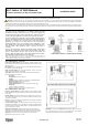
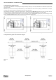
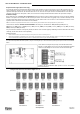
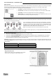
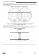
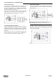
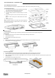
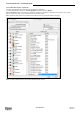
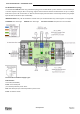
Table Of Contents

www.elpas.com
Page 1 of 12
V2/Dec 2014
ALC Indoor LF BUS Beacon
For P/N: 5-ALC01021-0 (no RF), 5-ALC01121-0 (RF)
Installation Guide
Introduction
This installation guide provides basic instructions for common ALC LF BUS Beacon installation scenarios.
CAUTION! It is important that you read and follow the instructions in this document. If you have questions, call your local Elpas support representative.
Reasonable effort was made to ensure that the specifications and other information in this guide are accurate and complete at the time of its publication. Nonetheless,
all information contained in this document is subject to change at any time without prior notice.
Any modifications to this equipment without prior written consent of Elpas Solutions Ltd. will void all warranties including the pertinent regulatory certifications and as
such revoke your authority to operate this product. Furthermore unauthorized modifications may also result in damage to this device and may cause a safety hazard to
the users.
Product Description
The Elpas ALC LF BUS Beacon is a 125KHz emitter that adds
instantaneous location, choke-point (a door or any other opening that
controls ingress and egress from a protected area), awareness to RTLS
security, and safety applications. 5-ALC01121-0 is also fully supervised.
The ALC LF BUS Beacon generates a user-adjustable, elliptically shaped
field up to 4m/13ft (perpendicular to the device) and 3.5m/11.5ft (parallel to
the device) in radius that can be used to cover a single interior doorway.
Optionally, up to three ALC LF BUS Beacons can be deployed in
‘Primary–Secondary’ (up to two secondary devices) topologies to cover
large double-doors or architectural complex indoor entrance/exit areas.
The DIP Switch setting determines which is primary and which is
secondary.
The ALC LF BUS Beacon contains two general purpose analog inputs
(IN1 and IN2) and two open collector outputs (OC1 and OC2). The device
forces a choice between IN2 and OC2. The device also provides the
choice of either two digital inputs or two 26-bit Wiegand device outputs.
The DIP Switches setting determines these selections.
Note: An Elpas RS-485 BUS may contain up to fifteen Elpas BUS devices (such as RF or IR
Readers, Elpas Display Panels, LF Beacons or other Primary BUS Beacons) which are wired
together with Elpas RS-485 Junction Boxes (P/N:5-JBA10485).
LF BUS Beacon (Primary) - Sample Network Topology
ALC LF BUS Beacons – Front View
Front Cover Tamper Contact: ALC BUS Beacons contain a tamper contact
which indicates non-authorized attempts to remove the device front cover tray
when in operation.
DIP Switches: ID DIP switches (see page 3 for details) and Mode Selection
DIP switches (see page 4 for details).
Range Selection Button: Next to the LED indicators. Used to control the
range of the LF field (see page 4 for details).
Status LED: All BUS beacons contain a Red, Green and Amber LED array
that detail the status of the devices:
Green LED
o Unregistered: Flashes once/second
Red LED
o Invalid ID: Flashes once/second - See page 4 for additional details
o Device Back Tamper: Flashes once/second
o Output Activated: Flashes once
o Synch Cable Disconnect (in secondary): Flashes continuously.
Orange LED
o Continuous indicates normal state
o Flashes to indicate the front cover is not properly closed
ALC LF BUS Beacons – Rear View
PCB Tray Tamper Contact: ALC BUS Beacons contain a tamper contact
which indicates non-authorized attempts to remove the device PCB tray when
in operation.
RS-485 Interface: ALC BUS beacons contain a female RJ-11 connector to
link to the RS-485 Junction Box. This connector transfers both power & data.
(See page 2 for details)
Buzzer: The beacon has a buzzer that sounds when an improper ID Address
is assigned. (See page 4 for details.)
General Purpose Inputs: ALC BUS Beacons include one fixed and one
selectable general purpose inputs. (See page 6 for details.). The beacons also
provide the choice of either two digital outputs or one 26-bit Wiegand device
output. (See page 6 for details.)
Output (User Selectable): The beacons provide the choice of either two
digital outputs or one 26-bit Wiegand device output. (See page 6 for details.).
The beacons also include one set and one selectable open-collector outputs.
Important: An electric current runs through the LF coil. The current is
especially strong at the vias. Do not touch.
ALC LF BUS Beacon (Front View-Cover Removed)
ALC LF BUS Beacon (Rear View)
IMPORTANT: BUS Beacons MUST BE powered-down while you wire the
unit’s I/Os and when you connect to the RS-485 BUS. This prevents
accidental damage to the devices caused by shorts/spikes.