
User's Manual

LF BUS Beacon – Installation Guide
www.elpas.com
Page 2 of 7
V22/Jan 2013
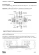
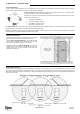
RS-485 BUS/Stub Topology
The RS-485 BUS MUST BE wired using a BUS/Stub topology where the BUS Master (a RF IP Reader or an ELC Controller) is connected
anywhere along the BUS. The topology supports data transmission between the BUS Master and up to 15 Elpas BUS Devices (such as RF or IR
Readers; LF Beacons primary & secondary), Elpas Display Panels and 6x6 I/O Modules using Elpas RS-485 Junction Boxes (P/N: 5-JBA00485).
IMPORTANT NOTE: Only 1 RF IP Reader/ELC Controller and up to 7 RF BUS Readers may coexist together on a single BUS.
200M/650Ft: Max. BUS length 10M/30Ft: Max. Stub length 100 Ohm Termination: Required each end of the BUS.
Recommended RS-485 Backbone Cable Type: CAT5 Solid (4x2x26AWG)
For Power: Use three-twisted pairs (six conductors) between RS-485 Junction Boxes
For Data: Use one-twisted pair (two conductors) between RS-485 Junction Boxes
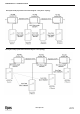
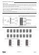
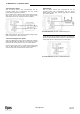
Primary/Secondary Synchronization
Up to four LF BUS Beacons can be deployed in ‘Primary–Secondary’ Daisy-Chain or Star Topologies in order to cover large double-doors or
architectural complex indoor entrance/exit areas.
When deploying either of these two topologies, the LF fields generated by the secondary beacons MUST BE synchronized to pulse at precisely
the same moment in time as the LF field generated by the primary unit in order to avoid mutual interference between any of the LF fields.
To implement Primary/Secondary Synchronization a Sync Data Link (typically using a 2x2x26 Category 5 cable) needs to be physically
connected between the Primary Beacon and all of the Secondary devices.