
User's Manual

www.elpas.com
Page 1 of 7
V22/Jan 2013
Elpas LF BUS Beacon
For P/Ns: 5-ALA00125-11, 5-ALA00125-12 & 5-ALA00125-2
Installation Guide
Introduction
This installation guide provides basic instructions for common LF BUS Beacon installation scenarios
CAUTION! It is important that you read, understand, and follow the instructions in this document. If you have questions, call your local Elpas support representative.
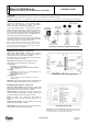
Product Description
The Elpas LF BUS Beacon is a fully supervised, 125KHz
emitter that adds instantaneous location (choke-point)
awareness to RTLS security and safety applications
The LF BUS Beacon generates a user-adjustable, spherical
shaped electromagnetic field up to 1.5m/5ft in radius that can
be used to cover a single interior doorway. Optionally, up to
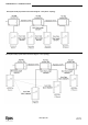
four LF BUS Beacons can be deployed in ‘Primary–Secondary’
star or daisy-chain topologies to cover large double-doors or
architectural complex indoor entrance/exit areas
The LF BUS Beacon also contains an I/O port that enables the
monitoring of one alarm sensor and control of either one digital
open-collector output or one 26-bit Wiegand device
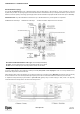
Note: An Elpas RS-485 BUS may contain up to fifteen Elpas BUS
devices (such as RF or IR Readers, Elpas Display Panels, LF Beacons
or other Primary BUS Beacons) which are wired together using Elpas
RS-485 Junction Boxes (P/N:5-JBA00485).
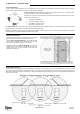
LF BUS Beacon (Primary) - Sample Network Topology
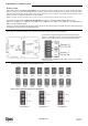
Primary/Secondary Beacons – Front View
Front Cover Tamper Switch: All BUS beacons contain a
tamper switch which indicates non-authorized attempts to
remove the device’s front cover when in operation.
The tamper switch is also used to control the coverage area of
the LF field. (See page 4 for details.)
Status LED: All BUS beacons contain a Red, Green and
Orange LED array that detail the status of the devices:
Green LED
o Unregistered: Flashes once/second
o Power up/Communication Loss/Sync Cable Disconnected:
Flashes once/second
Red LED
o Invalid ID: Flashes once/second - See page 4 for additional details
o Device Tamper: Flashes once/second
o Output Activated: Flashes once
Orange LED
o Flashes to indicate the selected LF field range - See page 5 for
additional details
DIP Switch: Only the Primary Beacon has an eight-position DIP
Switch for assigning its ID Address. (See page 4 for details.)
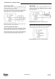
Primary/Secondary Beacons – Rear View
Rear Cover Tamper Switch: All BUS Beacons contain a dual
purpose tamper switch which indicates non-authorized attempts
to remove the device’s rear cover when in operation.
RS-485 Interface: All BUS beacons contain a female RJ-11
connector for linking to the RS-485 Junction Box. This connector
is used for both power & data. (See page 2 for details)
Buzzer: The beacon has a buzzer that sounds when an
improper ID Address has been assigned. (See page 4 for
details.)
General Purpose Inputs: All BUS Beacons have general
purpose inputs. (See page 6 for details.)
Digital Output: The primary beacon and the secondary beacon
have one digital output. (See page 6 for details.)
LF BUS Beacon (Front View-Cover Removed)
LF BUS Beacon (Rear View)
IMPORTANT: BUS Beacons MUST BE powered-down while wiring the
unit’s I/Os and when connecting to the RS-485 BUS. This will prevent
accidental shorts/spikes to cause damage to the devices