
User's Manual

VisAccess RDK-4– Installation Guide
www.elpas.com
Page 2 of 3
DE6321_V4_09/13
5. SECURITY LEVEL SELECTION
The RDK-4 can be programmed by the installer to offer one of
three security levels, as shown in the next table.
No.
Security level
description
Security level selection
1
The door is unlocked
by presentation of a
valid tag/card only.
No jumper is not installed .
2
Door is unlocked by
presentation of a valid
tag/card followed by
user PIN code
keying.
Select this security level by either
of the following actions:
A. Install jumper in the RDK-4.
B. Connect shorting wire
between D.POS & GND
terminals in the RDK-4 (see
fig. 4).
C. Set To/From time in minutes,
in AXS-100 registers 8 & 9
(for Reader 1) or registers 10
& 11 (for Reader 2), to
determine the period during
which the RDK-4 will switch
from security level 1 (tag
only) to security level 2 (tag +
PIN). For example, if you
want that the security level 2
will be valid from 12 o’clock
(720 min.) to 13 o’clock (780
min.), set AXS-100 register 8
to 720 and register 9 to 780.
For details, refer to AXS-100
User Guide par. 3.2.7.
3
Door is unlocked by
Password keying
followed by pressing
the # key
Set AXS-100 password as
described in the AXS-100 User
Guide par. 3.3.3.
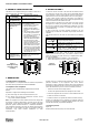
Figure 4
Selecting Security
Level 2 by Using
a Jumper
external
reader
Jumper
RDK-4
6. USING THE RDK 4
To enroll an access card refer to the AXS-100 User Manual section
3.3.1 Add Keys. The PIN code of each card is automatically defined
by the AXS-100. In order to receive the PIN codes for access cards,
please refer to the AXS-100 User Manual section 5.2.1 Setup Flags.
To enter a door, present a valid tag to the RDK-4. If your RDK-4 is
programmed to operate by tag and user’s PIN code, present the tag
and then enter the PIN code within 5 seconds.
When presented to an RDK-4, the access card or tag emits a coded
RF signal that is read by the proximity reader. The reader prompts
the user for a 4-digit PIN code by blinking the yellow light. If no PIN
code is typed within 10 seconds, or a wrong PIN code is typed, the
red LED will light up.
A delay of more than 5 seconds, between presenting a tag and
starting to key user PIN code, or between any two digits, cancels the
operation.
The normal functions of the LEDs are summarized in the following
table.
LED
Function
Green
Indicates that a valid tag was presented and
the output relay was activated.
Red
Indicates that an invalid tag was presented or
an invalid PIN was entered.
Yellow
Remains lit to indicate that power is on. In
security level 2, blinks after the tag is
accepted, to prompt the user for PIN.
Job Control
There is an option that when a valid exit occurs, the exit will be
reported (Time & Attendance exit), if the reader is defined in EXIT
mode (see AXS-100 user guide, section 4). To implement this option,
ther are 2 possibilities:
1. Before opening the door, press the “” key in the RDK-4.
2. Before opening the door, press the RTE switch (see fig. 5).
Figure 5
RTE switch
external
reader
RTE
switch
RDK-4
7. REGULATORY
7.1 EU Declaration of Conformity
This equipment is in compliance with the essential requirements
and other relevant provisions of Directive 1999/5/EC.
7.2 Compliance FCC Compliance
This device (FCC #:O4X3-63210) complies with FCC Rules
Part 15.
Operation is subject to the following two conditions:
(1) This device may not cause harmful interference, and
(2) This device must accept any interference received, or that
may cause undesired operation.
Note: This equipment has been tested and found to comply with
the limits for a Class B digital device, pursuant to part 15 of the
FCC Rules. These limits are designed to provide reasonable
protection against harmful interface in a residential installation.
This equipment generates; uses and can radiate radio frequency
energy and, if not installed and used in accordance with the
instructions, may cause harmful interference to radio
communications
However, there is no guarantee that interference will not occur in a
particular installation. If this equipment does cause harmful
interference to radio or television reception, which can be determined
by turning the equipment off and on, the user is encouraged to try to
correct the interference by one or more of the following measures:
• Reorient or relocate the receiving antenna.
• Increase the separation between the equipment and receiver.
• Connect the equipment into an outlet on a circuit different from that
to which the receiver is connected.
• Consult the dealer or an experienced radio/TV technician for help.
Changes or modifications to this equipment not expressly approved
by the party responsible for compliance (Elpas Solutions Ltd.) could
void the user’s authority to operate the equipment.
7.3 Company Contact
Elpas, Inc.
Westford, Massachusetts (USA) -Tel: 1-800-223-0020