
User`s guide

CARROLL TOUCH Chapter 5 - Testing Touch System Hardware and Software
Touch System Diagnostics (CTDIAG) User’s Guide 5-9
Touch Coordinates screen appears, but non-contiguous messages appear
unexpectedly.
• Make sure you are only interrupting the infrared beam with one
finger - use a pen as a stylus to make sure. If messages persist, the
frame may have failed beams. If you are using an HBC or RS-232
controller, use scan reporting to check further.
Touch Coordinates screen appears, but there are dead spots on the
screen.
• Make sure you are using your finger or a stylus that is at least 5/16”
diameter. The infrared frame may have failed beams. Use scan
reporting to check further.
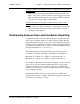
Relationship between Scan and Coordinate Reporting
As mentioned earlier, the touch software interprets the physical beam
data to report touch information. To achieve finer resolution than the
physical infrared beam grid provides, the touch software interpolates a
virtual beam between each pair of physical beams. The physical beams
are assigned even numbers (0, 2, 4, and so on) and the virtual beams are
assigned odd numbers (1, 3, 5, and so on).
The relationship between physical beams (scan reporting) and x, y
coordinates (coordinate reporting) is determined by the equations:
Maximum x coordinate = 2 * (number of x physical beams - 1)
Maximum y coordinate = 2 * (number of y physical beams - 1)
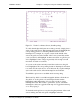
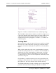
For example, in the infrared screen shown in Figure 5-1, the x axis has
a range of 0 to 63, representing 64 physical beams (scan reporting).
Using the equation (2 * 64 - 1) yields a result of 127, which is the
number of x coordinates in the same example infrared screen in Figure
5-2 (coordinate reporting).
Detailed information on the use of physical beams, virtual beams,
logical beams, logical coordinates, and beam averaging is found in the
Touch System Programmer’s Guide
.