
User`s guide

CARROLL TOUCH Chapter 5 - Testing Touch System Hardware and Software
Touch System Diagnostics (CTDIAG) User’s Guide 5-5
If you are using a serial (RS-232) controller or a Smart-Frame:
• Check that power is supplied to the RS-232 controller or
Smart-Frame.
• Check that the communication cable is properly connected to the
correct comm port.
• Ensure that the controller or Smart-Frame jumpers (if any) are set to
either autobaud or to a fixed baud rate and parity that matches those
shown on the Status line.
• Ensure that the stop bits parameter on the Status line is set to 1.
• Check that the port parameter on the Status line is set to the comm
port to which the touch system is connected.
Testing Software with Coordinate Reporting
When a finger or stylus interrupts an infrared beam or guided wave, the
software detects that interruption and reports a touch. In coordinate
reporting, the touch is reported in x, y coordinates. This type of reporting
is most useful for checking the functionality of the software.
Using Coordinate Reporting
To start coordinate reporting, take the following steps:
1. From the Test Configuration Menu (Figure 3-1), press ENTER to
display the Test Menu.
2. From the Test Menu (Figure 4-1), select the Touch Coordinates
option.
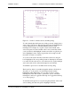
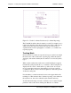
3. When the Touch Coordinates screen appears (Figure 5-2), type R to
enter coordinate reporting.
Note that, for the example infrared system, the X = value at the top of
the screen displays a range of possible values for x coordinates from 0
to 126. Similarly, Y = displays a range of y coordinates from 0 to 94.
Because the
Beam Trap Mode
operates with physical beams, not x, y
coordinates, it is not an available option within coordinate reporting.